
Last updated on August 27th, 2026 at 11:02 am
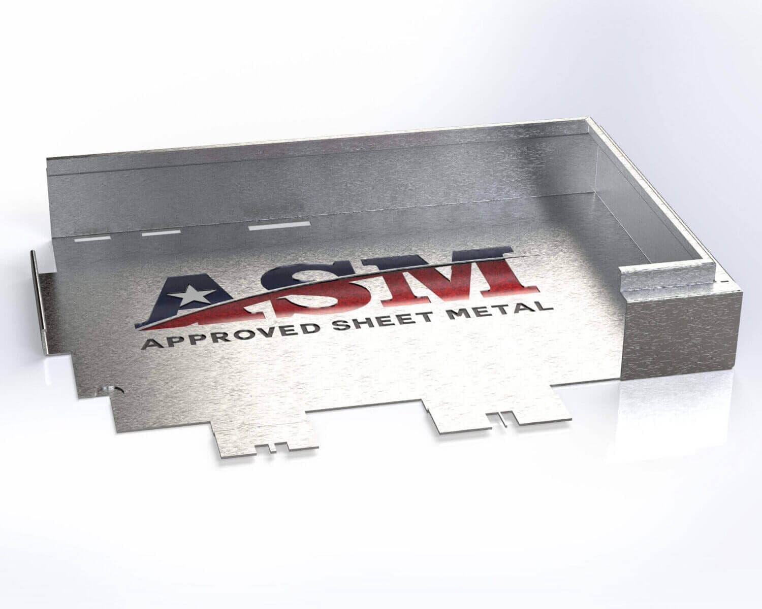
With all the metal enclosures we fabricate at Approved Sheet Metal (ASM), it’s no surprise that we also fabricate a significant quantity of sheet metal fabricated covers.
A sheet metal cover is only successful if it fits the enclosure or assembly it mates with. That means engineers need to account for material thickness, bend geometry, tolerance stack-up, hardware, access, finishing, and how the cover will be installed or removed.
Here’s what to consider when designing high-quality covers that fit, function, and assemble the way you expect.
Fabricated Covers from Approved Sheet Metal
Covers are most commonly designed as part of an assembly along with a box, enclosure, chassis, frame, or other fabricated component.
Depending on the design, a cover can help protect internal components from physical contact, debris, light, or environmental exposure. If the finished assembly must meet a specific ingress, sealing, electrical, or environmental requirement, that requirement should be designed into the complete enclosure rather than assumed from the cover alone.
Most covered enclosures include hardware such as screws, self-clinching fasteners, captive hardware, hinges, latches, or locks depending on the required level of access and serviceability.
Common Sheet Metal Cover Styles
The right cover style depends on how frequently the assembly must be accessed, how the cover should be removed, and how much overlap or sealing is required.
| Cover Style | Typical Use | Main Design Consideration |
|---|---|---|
| Flat Removable Panel | Access panels and simple equipment covers | Fastener spacing and panel stiffness |
| Formed Lid | Boxes, trays, and enclosures | Fit over or inside the mating enclosure |
| Slip-Over Cover | Protective housings and removable shells | Intentional clearance around the mating part |
| Hinged Cover | Frequently serviced equipment | Hinge axis, swing clearance, and latch location |
| Lift-Off Cover | Service panels and removable doors | Removal direction and clearance |
| Captive-Screw Cover | Equipment requiring repeated access | Hardware placement and serviceability |
| Gasketed Cover | Applications with sealing requirements | Gasket compression, flange geometry, and fastener spacing |
Top Materials for Fabricated Covers
When you leverage our sheet metal services to fabricate a cover, the best material depends on weight, stiffness, corrosion resistance, forming requirements, finish, and cost.
| Material | Why Engineers Choose It | Cover Design Consideration |
|---|---|---|
| 5052 Aluminum | Lightweight, corrosion resistant, and highly formable | Excellent for formed covers and enclosures |
| Cold-Rolled Steel | Cost effective and relatively stiff | Usually requires a protective finish when corrosion resistance is needed |
| 304 Stainless Steel | Durable and corrosion resistant | Higher material and fabrication cost than standard steel |
| 316 Stainless Steel | Greater corrosion resistance in more demanding environments | Higher material cost and may require additional forming consideration |
Primary Uses for Sheet Metal Covers
Precision sheet metal covers are used throughout electronics, medical equipment, industrial machinery, communications equipment, test systems, aerospace, defense, and other applications.
They may function as vertical doors, horizontal lids, removable access panels, equipment guards, cosmetic housings, or protective covers for internal electronics and mechanical components.
How ASM Fabricates Sheet Metal Covers
Precision sheet metal covers can look simple, but a finished cover may require several fabrication processes:
 Laser cutting
- Punching
- Forming
- Welding
- Grinding and weld finishing
- Hardware insertion
- Assembly
- Finishing
The final manufacturing sequence depends on the cover geometry, hardware, mating assembly, cosmetic requirements, and finish.
Design the Cover and Enclosure as One Assembly
One of the most important cover-design rules is simple: do not design or tolerance the cover in isolation if its primary function is to fit another fabricated part.
The final fit between a cover and its mating enclosure can be affected by:
- Material thickness
- Bend radius
- Forming tolerance
- Tolerance stack-up across multiple bends
- Weld distortion
- Powder coat or plating buildup
- Gasket thickness and compression
- Hardware location
- Hinge geometry
For this reason, ASM strongly recommends sending the cover and its mating enclosure, box, chassis, or frame in the same RFQ.
If we receive the two components separately, we may not know they are intended to fit together. Sending your assembly design files at the same time allows us to evaluate the functional relationship between the components during DFM review.
Build Intentional Clearance Into the Cover
A slip-over, nested, or overlapping cover generally needs intentional clearance between the cover and the mating enclosure.
The correct amount is not one universal number. It depends on:
- Part size
- Material thickness
- Number of formed bends
- Cover depth
- Required fit
- Finish thickness
- Whether both mating components are coated
A cover designed to exactly match the nominal outside dimensions of another formed sheet metal part may fit in CAD but interfere once normal forming tolerances and finishing are introduced.
If the exact cover-to-enclosure fit matters, identify that functional relationship on the drawing and allow the fabricator to review the required clearance before production.
Designing Sheet Metal Covers for Fabrication
Before releasing a cover for production, connect with the engineers at ASM and request a design review. We’ll review the cover along with the mating geometry and identify potential manufacturing, fit, hardware, or finishing concerns.
DFM Tips for Fabricating Sheet Metal Covers
- Design with the actual fabrication process in mind. Use bend radii, flange sizes, hardware, and features that align with available sheet metal processes and tooling.
- Pick common materials, hardware, and finishes. Readily available specifications generally reduce sourcing time and cost.
- Allow for tolerance stack-up. Identify the dimensions that control cover fit rather than applying unnecessarily tight tolerances to every individual bend.
- Send your assembly in a single RFQ. Providing both the cover and mating component allows ASM to evaluate the actual fit rather than reviewing each component independently.
- Use ASM’s Engineer’s Toolbox. Our reference charts, SOLIDWORKS resources, and CAD tooling library can help you design around common tooling and fabrication practices.
Keep Large Sheet Metal Covers Stiff
A large flat cover may fit correctly but still flex, vibrate, or develop visible oil-canning if the design does not provide enough stiffness.
Increasing material thickness is one option, but it is not always the most efficient solution. Formed geometry can often add substantial stiffness without the same increase in weight.
Common stiffening features include:
- Return flanges around cover edges
- Hems for stronger exposed edges
- Ribs or beads in larger flat areas
- Embossments where appropriate
- Shallow formed edges
- Additional mounting points when required
Stiffening geometry should be balanced against forming access, hardware location, cosmetic requirements, and available tooling.
Fastening and Mounting Options for Sheet Metal Covers
The way your sheet metal cover is fastened or mounted plays a major role in serviceability, assembly time, appearance, and cost.
Start by deciding how frequently the cover needs to be removed and whether loose hardware is acceptable.
| Access Requirement | Typical Solution |
|---|---|
| Rare or permanent access | Screws, bolts, rivets, or welded attachment |
| Repeated service access | Captive screws or reusable threaded hardware |
| Tool-less access | Quarter-turn or other quick-release fasteners |
| Hinged access | Hinge plus latch or captive fastener |
| Removable panel with no loose hardware | Captive fasteners or lift-off hinge systems |
PEM® and Self-Clinching Hardware
Self-clinching nuts, studs, and standoffs can provide reusable threaded attachment points in relatively thin sheet metal.
Always follow the hardware manufacturer’s minimum sheet-thickness, hole-size, hardness, and edge-distance requirements rather than applying one universal edge-clearance rule.
Captive Hardware
Captive screws and panel fasteners stay attached to the cover when loosened, which can be useful when technicians repeatedly remove a service panel or when dropped hardware would be undesirable.
Quarter-Turn and Tool-Less Fasteners
Quarter-turn fasteners can provide rapid repeated access without fully removing loose screws. They are useful for service panels, equipment doors, and other frequently accessed components.
Hinges and Latches
If the cover will remain attached to the assembly, hinges can simplify repeated access. The design should account for hinge axis, opening angle, internal clearance, door overlap, and latch location.
Use Alignment Features
Tabs, slots, pins, shoulders, and guide flanges can help locate the cover before fasteners are tightened. These features can reduce assembly time and help prevent cross-threading or incorrect orientation.
Include Hardware Specs in the Drawing Package
Whenever possible, include the exact PEM® or hardware manufacturer and part number in your 2D print, BOM, or 3D design package.
This removes ambiguity and gives your sheet metal fabricator the information needed to design the correct hole size, material thickness, and installation sequence.
Account for Finish Before Finalizing Cover Fit
Finishing can change the final dimensions and fit of a fabricated cover.
Powder coating, plating, anodizing, chromate conversion, and other processes can affect mating clearances, threads, hardware, hinges, and contact surfaces.
Powder coating is especially important to consider on a slip-over or nested cover because both mating surfaces may receive coating. The combined buildup can reduce the clearance between components.
If a drawing dimension must apply after finishing, identify that requirement clearly.
Critical mating, grounding, threaded, bearing, or locating surfaces may also need masking depending on the application.
Ventilation and Other Features in Sheet Metal Covers
Covers frequently carry functional features such as:
- Louvers
- Perforations
- Fan cutouts
- Connector openings
- Displays
- Switches
- Handles
- Labels or graphics
Large ventilation patterns or cutouts can reduce cover stiffness, so their location should be evaluated along with bend geometry, material thickness, and mounting points.
If the cover is part of an electronics enclosure, consider ventilation and thermal requirements before the geometry is finalized rather than simply adding openings at the end of the design process.
Finishes for Sheet Metal Covers
ASM provides in-house and vendor-managed finishing options depending on the material and application.
- Powder coating: Provides a durable protective and cosmetic finish in many colors and textures.
- Anodizing: Commonly used on aluminum when corrosion resistance, appearance, color identification, or surface hardness is important.
- Chromate conversion: May be specified on aluminum for corrosion protection or as part of another finishing system.
- Plating: Zinc, nickel, and other plating processes may be appropriate depending on material, corrosion, electrical, or appearance requirements.
- Silk screening: Allows labels, graphics, logos, switch identifiers, and other markings to be added to a cover.
- Wet paint: May be appropriate when color matching, multiple colors, touch-up requirements, or another coating specification makes powder coating less practical.
The finish should be selected based on material, environment, appearance, electrical requirements, service conditions, and final assembly fit.
What Should You Include in a Sheet Metal Cover RFQ?
Providing the complete assembly information helps ASM evaluate fit, tolerances, forming, hardware, finishing, and access requirements before fabrication begins.
When possible, include:
- 3D model of the cover and mating assembly
- 2D drawing identifying critical dimensions and tolerances
- Mating enclosure, box, chassis, or frame design
- Material and thickness
- Critical cover-to-enclosure clearances
- Hardware manufacturer and part numbers
- Hinge and latch requirements
- Gasket specification, when applicable
- Finish specification
- Masking requirements
- Cosmetic surfaces
- Ventilation or functional openings
- Serviceability and removal requirements
The more clearly the mating relationship is defined, the easier it is for ASM to focus its DFM review on the features that control the cover’s actual fit and function.
Get Custom Sheet Metal Covers from ASM
Our team has extensive experience fabricating covers across a wide range of dimensions, materials, fastening methods, and styles.
Whether we’re fabricating the entire assembly or the cover alone, we review the part with forming, fit, hardware, finishing, and final use in mind.
For the best results, send the cover and its mating components together so our team can evaluate them as a complete assembly rather than unrelated individual parts.


