
Last updated on August 28th, 2026 at 09:26 am
Approved Sheet Metal fabricates a wide range of sheet metal assemblies for customers, from small sub-assemblies to massive frame assemblies—all without breaking the bank.
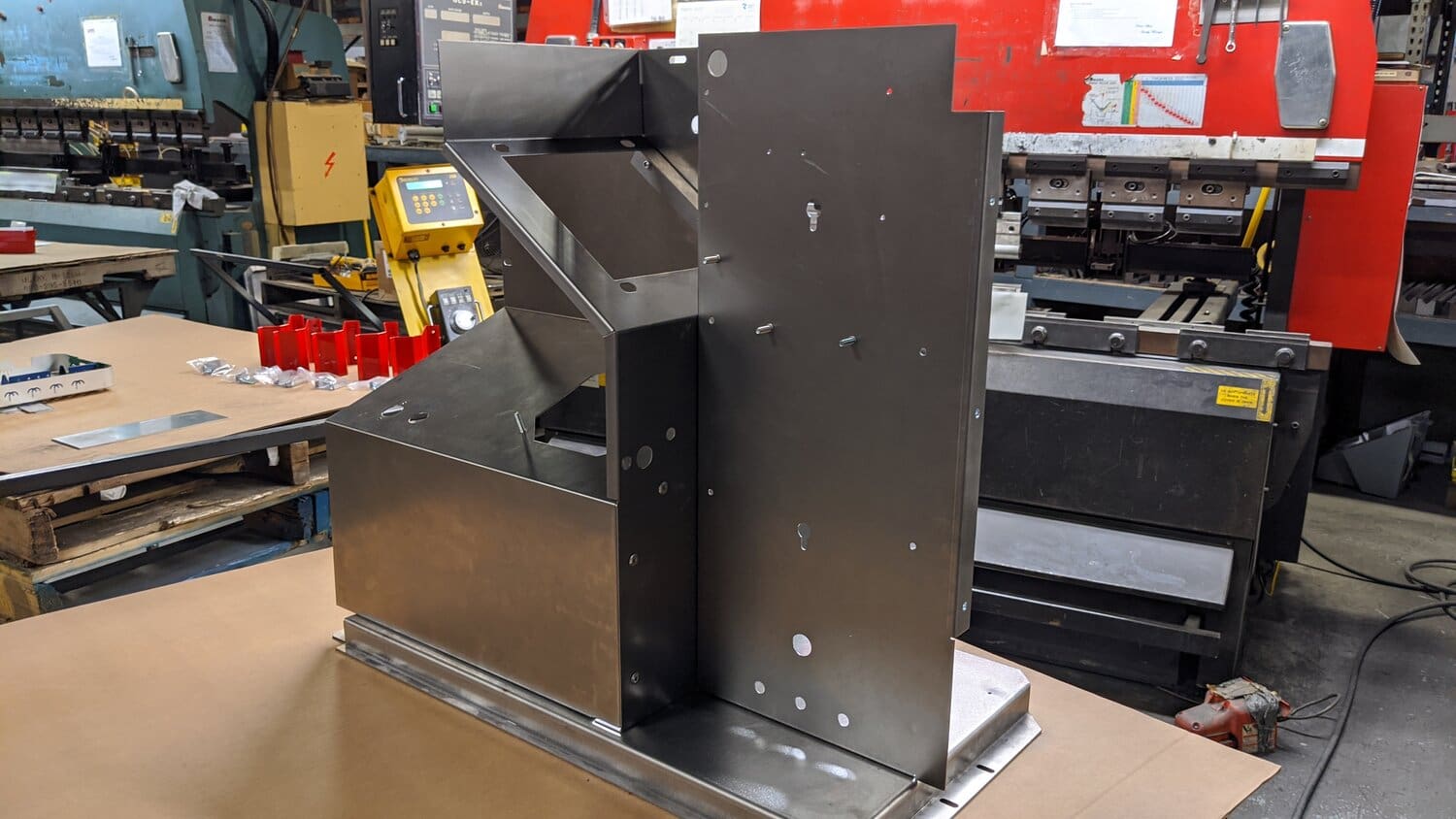
Regardless of size, assemblies present quite a few unique challenges that not every fabricator is equipped to identify, let alone address. However, at ASM, we know how to help you avoid these challenges altogether with our expert sheet metal services.
With these proven design principles and a few clever hacks, you’ll be set to design sheet metal assemblies that fit and function as needed:
1. Pay Attention to the Assembly’s Tolerance Stack-Up
We frequently talk about tolerancing for individual sheet metal fabrications, but tolerancing is more complex with assemblies. In addition to assigning tolerances to individual components, you must consider the tolerance stack for the entire assembly.
We often discover that once multiple components are fitted together, specified assembly tolerances simply aren’t possible to achieve with welding.
Make use of these ASM engineering resources to keep a close eye on your assembly’s tolerances:
2. Select the Best Assembly Method
Welding isn’t the only assembly method we offer with our sheet metal services. When heat distortion is a concern or welding simply can’t accomplish your goals, consider using pop rivets or screws to assemble your project.
If you’re looking for a fastening solution you don’t see here, talk to our team. Because assemblies often involve purchased components, remember to tell us if you want these items sourced from a specific supplier.
3. Prioritize Alignment and Fitment for Assembly Components
If your assembly’s modeling is even the slightest bit misaligned, our engineers will need to modify your design to ensure proper fitment. In most cases, alignment issues occur when an assembly’s design doesn’t include enough “wiggle room” to allow the individual components to shift and fall into alignment.
4. Consider the Assembly’s Surface Finish
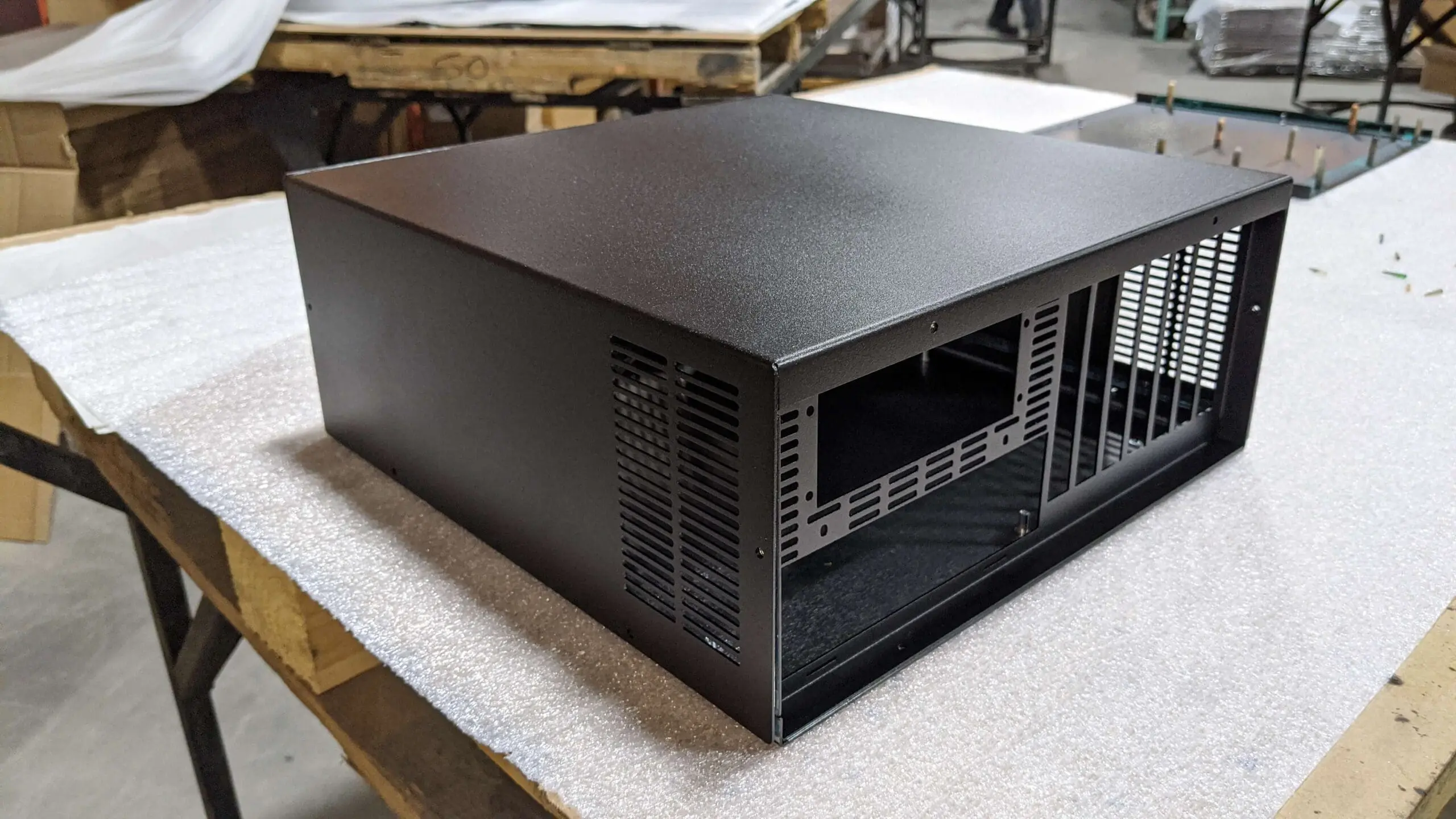 We understand that surface finish is essential to an assembly’s appearance, performance, and compatibility with secondary finishing processes such as powder coating or painting. Sheet metal finish considerations aren’t inherently complicated, but overly large assemblies can introduce unexpected costs and logistical challenges.
One ASM customer recently required a hand-polished surface for their oversized stainless steel assembly—a requirement that can be costly and time-consuming to achieve.
While there’s little we won’t do to meet our customers’ needs and expectations, we also like to help by identifying solutions that slash costs and lead times. If you ask for an unusually challenging finish, don’t be surprised if we reach out to make sure you understand the implications of your request.
5. Set Up Your SOLIDWORKS Assembly File
Finally, you’ll want to correctly structure your assembly’s SOLIDWORKS file to facilitate efficient quoting, fabricating, and assembly.
At ASM, we use an automated upload system that analyzes parts and assemblies to build an estimate. Quoting assembly jobs can be complicated and time-consuming if the assembly file isn’t set up and saved properly.
This quick, two-minute video demonstrates how to make a well-organized assembly file that interacts seamlessly with our upload system.
What You’ll Learn
As you’ll see in SOLIDWORKS Tech Tip #7: Setting Up Assemblies in SOLIDWORKS, you should structure your assembly file like this:
- Save the individual components as SLDPRT part files
- Add the components to an assembly file
- Mate the components to form the assembly
- Save the SLDASM assembly file
This approach gives ASM the individual component geometry along with the complete assembly relationship without requiring us to rebuild the assembly from separate files.
If you use another CAD platform, provide the complete 3D assembly along with the individual component models whenever possible. A STEP assembly can be especially useful for communicating how the parts are intended to fit together.
Providing a complete, organized assembly package can reduce engineering questions and help us build a faster, more accurate quote.
SUBSCRIBE to our YouTube channel for more SOLIDWORKS Tech Tips!
Overcoming Design Challenges for an Ultra-Complex Assembly
A customer brought a complex asymmetrical assembly to ASM for sheet metal fabrication and assembly. The design consisted of three unique components, each with numerous formed features and unusual geometry.
The challenge was not whether each individual component could be fabricated. The bigger issue was how the three components would fit together.
When our team reviewed the assembly model, we found significant gaps between mating components. Those gaps would have made it difficult to locate, fixture, and weld the parts into the intended final geometry.
Before fabrication began, the customer worked with ASM’s engineering team to refine the mating geometry and improve the relationship between the individual components.
This is exactly why we recommend submitting the complete assembly rather than sending each sheet metal part independently. Seeing the parts in context allows us to evaluate the actual assembly fit before material reaches the floor.
Account for Secondary Processes in Assembly Fit
When designing sheet metal assemblies, remember that fabrication is not always complete when the parts leave the press brake or welding department.
Secondary processes such as powder coating, anodizing, plating, and wet paint can affect mating clearances, holes, threads, hardware, grounding surfaces, and other close-fitting features.
The amount of buildup depends on the finishing process, coating specification, material, application method, and whether one or both mating surfaces receive finish. For that reason, there is no single clearance adjustment that works for every finished sheet metal assembly.
Designing Assemblies Around Finishing
Define Critical Mating Clearances
If two fabricated components slide over, nest inside, overlap, or otherwise fit closely together, identify that relationship as a functional requirement.
A clearance that works between unfinished parts may become tighter after one or both components receive a coating.
Instead of applying a universal hole or clearance increase, define the finished fit you need and review it with your fabricator.
Mask Critical Features When Necessary
Some features may need to remain free of coating or other finish. Examples include:
- Threads
- Grounding points
- Electrical contact surfaces
- Precision mating surfaces
- Bearing or locating surfaces
- Selected hardware interfaces
Clearly identify masking requirements on the drawing so the finishing process can be planned before production.
Plan Hardware and Finishing Together
Hardware may be installed before or after finishing depending on the fastener, coating, grounding requirements, cosmetic expectations, and customer specification.
For example, installing hardware before powder coating may require thread masking, while installing hardware after finishing may introduce a risk of damaging the finished surface during insertion.
Specify the exact hardware part number and any critical installation or finishing requirements so ASM can determine the appropriate sequence.
Identify Dimensions That Apply After Finishing
Do not simply change CAD geometry by an arbitrary amount to compensate for coating buildup.
Instead, model the intended finished part geometry and clearly identify any dimensions, holes, or mating relationships that must meet a requirement after finishing.
This gives the fabricator and finisher the information they need to determine whether additional clearance, masking, or another process adjustment is appropriate.
Prototype Critical Assembly Fits
For tight, unusual, or unfamiliar mating conditions, prototype testing can help confirm that the assembly fits and functions as intended before committing to a larger production quantity.
If finishing is expected to affect the fit, validation should include finished components rather than relying solely on an unfinished test assembly.
Design Assemblies for Alignment, Not Manual Adjustment
Assembly becomes easier and more repeatable when the design itself helps locate the components.
Useful alignment features can include:
- Tabs and slots
- Locating pins
- Pilot holes
- Datum surfaces
- Guide flanges
- Clearance holes
- Floating hardware
These features can reduce the amount of measuring and manual positioning required during assembly and welding.
Tabs and slots are particularly useful for creating self-fixturing sheet metal assemblies. They can establish orientation, help prevent incorrect assembly, and hold components near their intended position before welding or fastening.
They still need appropriate clearance, however. Tabs and slots should not be designed as zero-clearance features unless the application and manufacturing process specifically require it.
Account for Welding Distortion
Welding introduces heat into a sheet metal assembly, and that heat can cause the components to move as the welds cool.
The amount of distortion depends on factors such as:
- Material
- Material thickness
- Joint geometry
- Weld size
- Weld length
- Weld sequence
- Assembly size
- Fixturing
Long continuous welds or heavy welding on thin material can make dimensional control more difficult.
If an assembly has critical dimensions that must be maintained after welding, identify them clearly on the drawing. This helps ASM plan the welding sequence, fixturing, and inspection around the requirements that actually control form, fit, and function.
ASM Sheet Metal Fabrication and Assembly Services
Approved Sheet Metal focuses on rapid prototype and low-volume sheet metal fabrication, including formed, welded, hardware-intensive, and assembled components.
- We’re fabrication-focused. Our team specializes in custom sheet metal parts and assemblies rather than broader electrical or plumbing integration.
- Communication and collaboration matter. When an assembly presents a fit, tolerance, hardware, or fabrication challenge, our team works with customers to identify practical options before production.
- Assembly context helps us make better DFM decisions. Providing the full assembly model, individual component files, drawings, hardware information, and purchased mating components when relevant gives us a clearer picture of how the finished project needs to work.
```
```
Whether your project is a small subassembly or a large welded fabrication, designing around tolerance stack-up, alignment, welding distortion, hardware, and finishing can make the final assembly much easier to manufacture successfully.


