SOLIDWORKS Sheet Metal Design Videos
Our estimators bring decades of combined experience in metal fabrication, with deep roots in both hands-on shop work and advanced design practices. With extensive knowledge of SOLIDWORKS and other CAD tools, they work closely with customers to demonstrate how sheet metal parts are designed for efficient fabrication. Whether it’s helping engineers reduce costs, avoid common pitfalls, or streamline production, our team is dedicated to creating a smooth, cost-effective, and frictionless fabrication process.
Jump to Tip:
SOLIDWORKS Tech Tip #1
How to Flatten a Sheet Metal Part in SOLIDWORKS
The primary reason designers want to unfold their sheet metal part is to make sure it actually does unfold, without any issues. Issues can be dropped flanges due to non-uniform material thickness, overlapping bends, lack of bend relief, etc.
Just because a part unfolds with no issues does not mean that it can be manufactured as designed. Flat pattern dimensions that a designer comes up with will likely not be what their manufacturer has after adding their bend deductions. Bend deductions can differ from shop to shop depending on their tooling setup and if they are air bending or pressure bending.
SOLIDWORKS Tech Tip #2
Breaking up a Sheet Metal Part into Multiple Pieces so It Can Be Fabricated
One of the processes of sheet metal fabrication that is the most misunderstood is forming. While we do not expect our customers to be expert sheet metal mechanics, it is important to understand that just because a part unfolds it doesn't mean it can be fabricated as designed.
Press brakes and press brake tooling are limited in what they can do. This is why we prefer to explore options to break up a part if it cannot be formed in a single piece.
SOLIDWORKS Tech Tip #3
Unable to Unfold Part, Sheet Metal Bend Radius Issue Solved
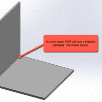
When designing sheet metal parts in SOLIDWORKS, it is critical that the parts are drawn as sheet metal. This ensures that the part unfolds and will flag any errors in the design. If the part doesn't unfold there is typically an error somewhere in the design. Drawing a radius manually to denote bends is fine as long as this simple rule is followed.
The external radius should be the internal radius + the material thickness. Please keep in mind that there are rules for internal bend radius too. We will cover that in a later video.
SOLIDWORKS Tech Tip #4
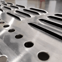
Louvers and Max Height
Punched louvers, embossments, bridge/lances, etc are very common features in sheet metal. These features should not exceed 3x-4x the material thickness in height from the top of the sheet to the top of the form.
If 3x - 4x is exceeded there is a high risk of the material cracking or tearing. This rule should be followed for all materials. Keep this in mind when designing these features, and as always, if you have any questions we are here to help.
SOLIDWORKS Tech Tip #5
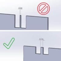
Designing Features Too Close to the Bend
Sheet metal features too close to bends are one of the most common design challenges we see as fabricators. So why is this a problem? Standard press brake tooling requires that any feature be 3-4x the material thickness away from the edge of a bend. Anything under that will deform or pull the material, stretching and causing the feature to not be useable or functional in the end product. We created a video so we could share a couple of ways to mitigate these challenges.
SOLIDWORKS Tech Tip #6
Slots & Tabs
Slots and tabs are features added to sheet metal parts to help align surfaces and assembly parts. This is done to assist in the welding process in order to avoid the need for fixtures and jigs. There can be many options depending on the manufacturer's welding process and standards, but they greatly reduce welding setup time as the features and parts interlock together to self-fixture.
Approved Sheet Metal does not require customers to have these features on their parts as it is done internally at the programming stage, but it is important to see how parts are prepped for welding.
SOLIDWORKS Tech Tip #7
Setting Up Assemblies in SOLIDWORKS
At Approved Sheet Metal we use an automated upload system that auto-analyzes parts and assemblies to get a faster estimate. Assemblies can be a challenge depending on how they are saved from our customers. In this video, we will highlight a way to make a clean assembly file that will upload in our system easily for a fast and accurate quote. This is also good practice for any SOLIDWORKS user as it is important to create and save clean assemblies.
SOLIDWORKS Sheet Metal Design Blogs
Introducing: Approved Sheet Metal’s Proprietary Louver Tool in SOLIDWORKS (Updated for 2025)
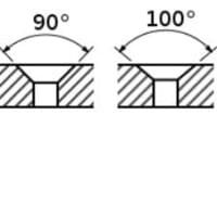
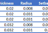
Get Approved Sheet Metal’s Proprietary Formula for Designing Countersinks (Updated for 2025)
Are You Using the Right Bend Radius for Your Precision Sheet Metal Formed Part? (Updated for 2026)
3 Tips for Designing a Custom Sheet Metal Part in SOLIDWORKS (Updated for 2025)