Last updated on March 10th, 2025 at 10:00 am
We admit it. We’re guilty. Here at Approved Sheet Metal, our fabricators casually toss out sheet metal fab terms like “DFM” and “oil canning”—we forget that not everyone speaks the language of sheet metal!
But the good news is you only need to learn a handful of common fabrication phrases to communicate like a true sheet metal services expert. With these words, designers, engineers, and buyers can collaborate optimally and bridge the knowledge gap between the design desk and the shop floor.
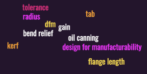
Add these top 10 sheet metal fab terms to your vocabulary to simplify your custom sheet metal fabrication experience:
1. DFM: Design for Manufacturability
This simple acronym, DFM, plays a massive role in the success of your fabricated parts. DFM (or Design for Manufacturability) is the engineering practice of designing parts for streamlined manufacturing, which results in lower costs and shorter lead times.
However, there isn’t one hard, fast set of DFM rules. While some DFM best practices are largely universal, many DFM guidelines are specific to the manufacturer. When it comes to ASM’s sheet metal services, for instance, we provide numerous resources to help you design parts that are compatible with our specific fabrication processes.
We even wrote a DFM eBook!
Download our DFM eBook:
Design Sheet Metal Parts with the Manufacturing Process in Mind
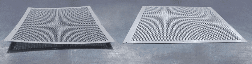
2. Oil Canning
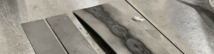
Oil canning is a slick term for deformation in sheet metal parts. While primarily an aesthetic concern, oil canning can throw off your part’s flatness tolerance, creating issues with fit and functionality.
Oil canning is a visible, wavy warping that can affect all types of metal. Welding tends to create the most intense oil canning, so we review our customers’ designs for welding requirements that will cause the part to deform.
There are a few ways to prevent oil canning in your custom sheet metal fabrication:
- Remove or open up your flatness tolerance callout
- Design your weldment with fewer pieces
- Opt for tack, stitch, or spot welding instead of full seams
- Utilize thinner material
We realize that preventive measures aren’t always possible, so rest assured that we will communicate any oil canning concerns we encounter when reviewing your part design, and we’ll do our best to identify a solution!
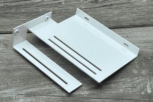
3. Flange Length
In sheet metal fabrication, the flange length (or flange height) is the distance between the bend and the part’s edge or the next feature, such as a hole or another bend.
If a flange is too short, the sheet metal will slip into the v-shaped die during forming, preventing us from bending the material.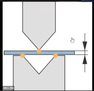
Lucky for you, we developed a simple flange formula to help you design your part’s flanges to the appropriate length:
4x Material Thickness + Bend Radius = Minimum Acceptable Flange Length
Keep that formula handy, and you’ll never need to worry about flange length again!
4. Bend Radius
Fabricators can only bend sheet metal so far before damaging it, and we call that smallest possible inner curvature the bend radius (or internal radius.)
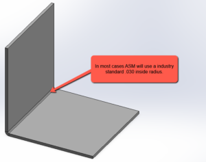
You can slash your lead time and avoid the high cost of custom tooling by designing your part’s bend radius to 0.030"—the industry standard for sheet metal up to 0.125" (⅛") thick.
While we’re on the topic of bend radii, allow us to clear up a few misconceptions:
- The bend radius is not determined by a fabricator’s tooling
- The bend radius does not affect the part’s flange length
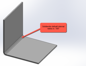
- SOLIDWORKS’ default bend radius is not possible to achieve without expensive custom tooling
- Designing a bend radius equal to the material thickness is not a fail-proof solution
If your sheet metal is thicker than 0.125" or you’re still uncertain about the best approach to your part’s bend radius, reach out to our team for guidance.
5. Gain
When we form sheet metal into a bend, the outside of the material stretches while the inside compresses. This bend-and-stretch process lengthens the sheet metal’s exterior, and we refer to that bit of added length as the “gain.”
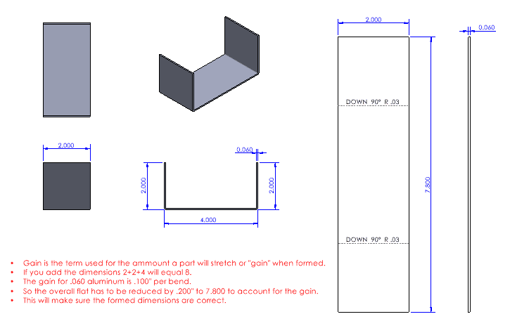
To calculate a part’s sheet metal bend gain, ASM developed a formula that accounts for the material type, material thickness, and bend radius. These measurements inform our press brake programming so we can ensure your completed part matches the print.
Because we use an in-house formula to calculate gains, you don’t need to modify your flat pattern one bit. Leave the gains calculations to us, and we guarantee that your part will be fabricated to your specifications.
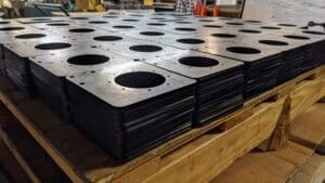
6. Bend Relief
To successfully bend sheet metal, fabricators create a small cut on either side of the intended bend. The cut is called a bend relief, and it protects the material from tearing and deformation during the bending process.
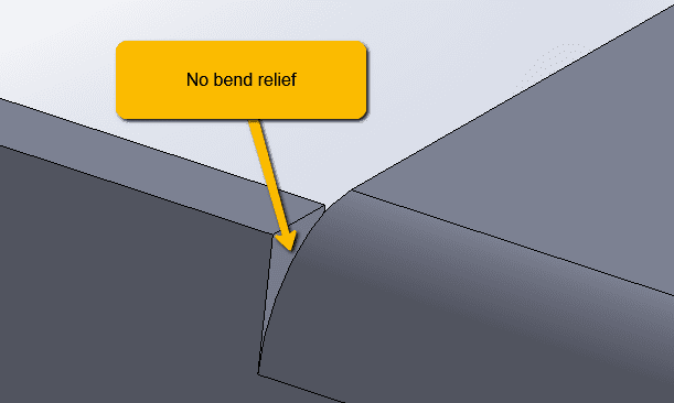
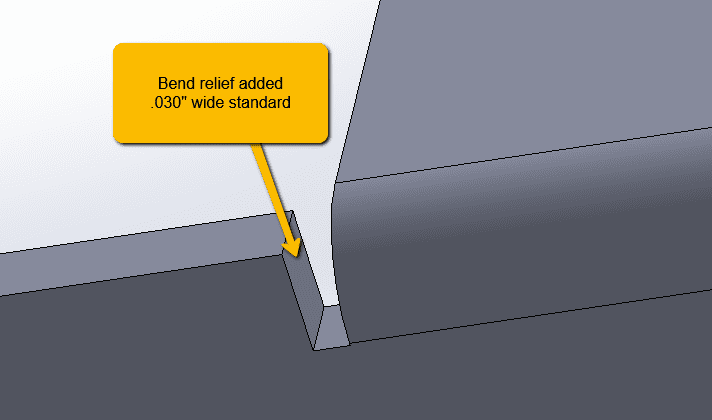
If your part’s design doesn’t include a bend relief, no need to worry. We’ll add a standard 0.030” bend relief—after talking to you first, of course. Or you can learn how to add your own bend reliefs in SOLIDWORKS!
7. Tolerance Stackup
When we talk about tolerance stackup, we’re referring to the total accumulation of tolerances within a component or assembly. Within a single part, the stackup includes each feature’s individualized tolerances. Within an assembly, each component’s tolerances stack according to how the parts align.
Imagine that you’ve designed a sheet metal part with the goal of achieving an overall tolerance of +/- 0.001”. Now, assume that the part requires multiple bends, each with its own +/- 0.001” tolerance. Every time your fabricator adds a bend, the tolerances stack until the part’s overall tolerance grows to +/- 0.005” or +/- 0.006”, depending on the quantity and placement of the bends.
Assemblies present even greater challenges, with each assembled part increasing the tolerance stackup far beyond the overall assembly tolerance you originally wanted.
The best way to avoid tolerancing problems? Stick to ASM’s standard sheet metal tolerances. Or have a conversation with our sheet metal services team, and we’ll help you achieve your tolerancing goals!
8. Forming Tabs
When a part is designed with unusual angles that interfere with the bending process, we add forming tabs to the 3D model in SOLIDWORKS.
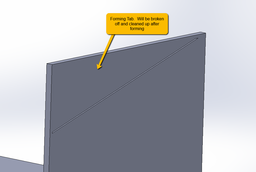
Why have you never seen forming tabs on any of your parts? Because we snap off the tabs and deburr the part before packing and shipping it!
The addition and removal of forming tabs does slightly increase the time and cost associated with custom sheet metal fabrication. But without the tabs, precise bends would be impossible to achieve. To be clear, we only use forming tabs on prototypes and low-volume orders that don’t justify the cost of a custom fixture. For a high-volume production, we forego the forming tabs and make a fixture instead.
9. Kerf
If your sheet metal part includes, say, an extra-long bend, you may hear us explain that we’ll be using a laser to create kerf cuts in the material, reducing its tonnage for bending. But what is kerf, anyway?
“Kerf” is a fabrication term for the ma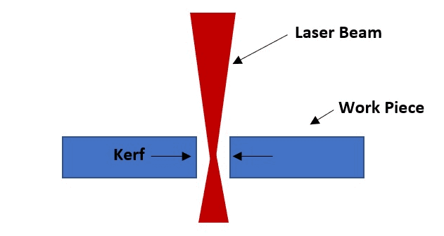 terial that burns away during laser cutting. Don’t worry about that minuscule amount of vaporized material; we’re pros at offsetting the kerf so the finished part meets your specifications.
The default kerf on most laser cutters is around 0.008” in diameter, but today’s machines will auto-adjust the kerf down to as narrow as 0.001”—especially when cutting in tight corners or meeting precision tolerances.
And those kerf cuts we mentioned? We’ll weld and clean up each one before delivering your part.
10. Crashing
This final fabrication term is the most logical of all. Crashing is what happens when we attempt to flatten a 3D model, and the part’s features collide, preventing unfolding. The word also describes a sheet metal part that into the tooling or even the machine itself due to the size of the part or its bend angles.
In some cases, we can prevent crashing by utilizing special tools, while other scenarios call for design modifications. If design revisions are necessary, we’ll connect with you to discuss options before proceeding.
11. Tolerancing Best Practices for Sheet Metal Fabrication
Precise tolerancing is crucial in sheet metal design to ensure manufacturability, cost-effectiveness, and assembly compatibility. Here are key best practices to follow:
1. Understand Standard Sheet Metal Tolerances
- Sheet metal tolerances are not as tight as machined parts due to material flexibility and forming processes.
- Standard tolerances typically range from ±0.005” to ±0.015” for bends and ±0.010” to ±0.030” for hole locations, depending on material thickness.
- Work with your fabricator to determine realistic tolerances instead of assuming overly tight specifications.
2. Account for Bend Tolerance and Springback
- During bending, metals experience springback, meaning the final bend angle may slightly differ from the intended design.
- Different materials have different springback rates—stainless steel has more than aluminum.
- Design bends with a consistent bend radius (e.g., 0.030” standard) to improve accuracy.
3. Avoid Overly Tight Tolerances in Multi-Bend Parts
- Each bend in a sheet metal part adds tolerance variation, leading to a tolerance stack-up issue.
- For designs requiring multiple bends, use progressive datum referencing instead of accumulating tolerances from a single edge.
4. Optimize Hole and Feature Placement
- Holes should be placed at least 2x material thickness from a bend to prevent deformation.
- Avoid positioning features too close to edges, as laser cutting or punching can cause material distortion.
- If high precision is required for holes, post-machining or reaming may be necessary.
5. Use GD&T When Necessary
- Geometric Dimensioning & Tolerancing (GD&T) can help define flatness, perpendicularity, and true position without overconstraining a design.
- Applying profile tolerances instead of tight linear dimensions allows for controlled flexibility during fabrication.
6. Work with Your Fabricator Early
- The best way to ensure cost-effective and accurate tolerancing is to collaborate with your sheet metal manufacturer during the design phase.
- Many fabricators offer DFM (Design for Manufacturability) reviews to suggest adjustments that reduce lead times and improve quality.
Bridging the Gap Between Part Design and Sheet Metal Services with Sheet Metal Fab Terms
At ASM, we’re committed to innovation, we believe in our team, and we value our customers. Helping design engineers and product developers bring their ideas to life is the heart of everything we do—and we would love to do that work for you!
Ready to work with us? Request a quote!