
Let Us Help You Get Bend Data Right
Last updated on September 2nd, 2026 at 01:38 pm
When a flat sheet metal blank is bent, material on the outside of the bend is placed in tension while material toward the inside is compressed. Accounting for that deformation is necessary to develop a flat pattern that produces the intended finished dimensions after forming.
For design engineers, this is where bend allowance, bend deduction, bend gain, and K-factor come into play. These values help connect the finished formed geometry in CAD to the flat pattern that will actually be cut and formed.
Bend Allowance vs. Bend Deduction vs. Bend Gain
These terms are related, but they are not interchangeable.
| Term | What It Describes |
|---|---|
| Bend allowance | The length of the neutral axis through the bend |
| Bend deduction | The amount deducted from the sum of the outside flange dimensions to calculate the flat length |
| Bend gain | A value used to relate formed dimensions to the developed flat pattern |
| K-factor | A ratio used to estimate the location of the neutral axis through the material thickness |
During bending, the outer surface stretches and the inner surface compresses. Between those regions is the neutral axis, where the material experiences much less change in length.
The location of that neutral axis is important because it affects the developed length of the flat blank.
Why Generic Bend Values Can Cause Problems
CAD software such as SOLIDWORKS can calculate flat patterns using a K-factor, bend allowance, bend deduction, or bend table. The challenge is that the result is only as accurate as the bend data entered into the model.
A generic K-factor or bend value may be useful during early design, but it may not match the material, tooling, and forming conditions that will actually be used in production.
Actual formed results can be influenced by:
- Material type
- Alloy and temper
- Material thickness
- Inside bend radius
- Bend angle
- Press brake tooling
- Die opening
- Forming method
- Material variation
- Springback
- Grain direction where applicable
Because of these variables, a fabricator may need to adjust the flat pattern supplied by the customer if the CAD bend parameters do not match the conditions that will actually be used to form the part.
The Role of Material Type and Thickness
Material selection has a major influence on how a part behaves during forming. Strength, ductility, temper, thickness, and springback can all affect the resulting bend geometry.
How Material Affects Bending
Different materials should not automatically use the same bend data, even when the finished bend angle appears identical.
For example, 5052-H32 aluminum, 6061-T6 aluminum, cold rolled steel, and stainless steel can respond differently to the same general forming operation.
Material-related factors include:
- Ductility: More formable materials can generally tolerate tighter bend geometry than less ductile materials.
- Strength and temper: These affect forming force, springback, and practical bend radius.
- Springback: Some materials recover more after the forming load is removed, requiring the forming process to compensate for the desired final angle.
- Grain direction: Rolling direction can affect bendability in some materials. When cracking risk is a concern, bend orientation should be considered along with alloy, temper, thickness, and bend radius.
How Thickness Affects the Flat Pattern
Material thickness is another important input, but thickness alone does not determine bend radius or bend gain.
The developed flat length is influenced by the relationship between material thickness, inside radius, tooling, bend angle, and the location of the neutral axis.
This is why bend data developed for one material thickness should not automatically be applied to another thickness, even if the part geometry is otherwise identical.
Example: Aluminum vs. Stainless Steel
Consider two parts with the same finished geometry, one made from 0.063" 5052-H32 aluminum and another made from 16 ga. 304 stainless steel.
Even if both parts require the same finished bend angle, the same generic bend value should not automatically be applied to both. Differences in material properties, thickness, springback, tooling, and resulting inside radius can change the developed flat length.
The important design lesson is not that one material always requires a larger or smaller bend deduction. It is that bend data should reflect the actual material and forming process being used.
Using Bend Data in SOLIDWORKS
SOLIDWORKS sheet metal models can generate flat patterns using several different bend-calculation methods, including K-factor, bend allowance, bend deduction, and bend tables.
The best approach is to use a consistent method and, when possible, use bend data provided by the fabricator that will actually form the part.
An accurate native sheet metal model remains extremely valuable because it communicates:
- Finished geometry
- Bend direction
- Flange relationships
- Feature locations
- Interference conditions
- Assembly intent
The fabricator may simply need to adjust the bend parameters or developed flat pattern to match its actual manufacturing process.
Let Us Calculate Your Bend Allowances (or Deductions) for You!
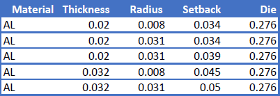
At Approved Sheet Metal, we aim to make your life (and ours!) easier. We created our own custom sheet metal bend gains chart so engineers and metal fabricators can always be on the same page. This information is our secret sauce, but we’re happy to share it with you.
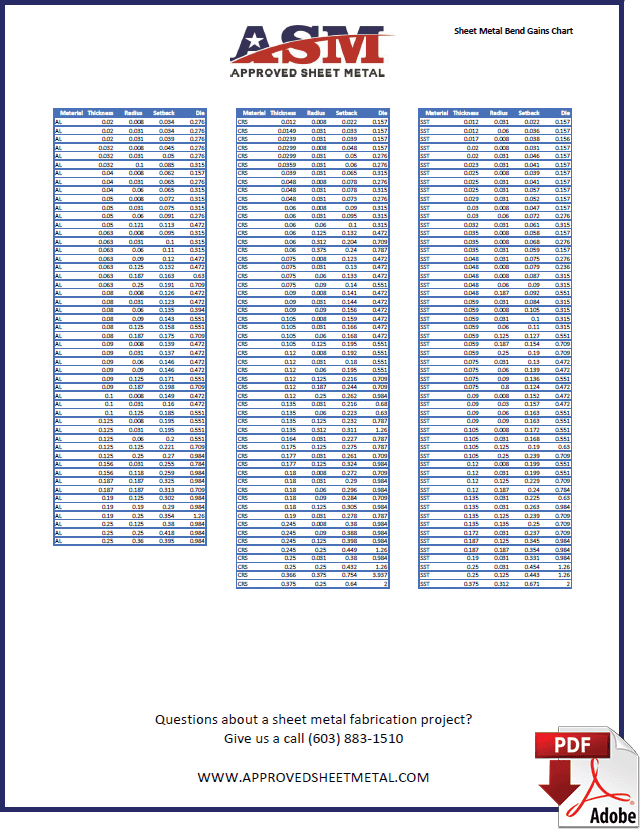
Sheet Metal Bend Gains Chart
BEND GAINS CHART DOWNLOAD
Don’t settle for K factor .5, use these specific bend gains so your manufacturer can use your native CAD model without them wasting time by having to recreate a flat pattern of your sheet metal fabricated parts.
We will review your CAD model along with the finished dimensions and tolerances that matter to the part.
The closer the bend data in your native sheet metal model is to the material, tooling, and forming conditions we expect to use, the closer the developed flat pattern will be to manufacturing reality.
For most formed parts, the drawing should focus on the required finished dimensions and tolerances after forming. The fabricator can then develop or adjust the flat pattern using bend data appropriate for the equipment, tooling, and material being used.
If you have questions about bend allowance, bend deduction, bend gain, K-factor, or how to set up your sheet metal CAD model, contact the ASM team.
You can also use our Sheet Metal Bend Gains Chart as a design reference for common material and forming conditions used at Approved Sheet Metal.


