Last updated on February 4th, 2026 at 09:20 am
Converting a solid part to a sheet metal part in software like SOLIDWORKS is important for several reasons:
- Material Efficiency: Sheet metal parts are typically designed to be fabricated from a single sheet of material, reducing waste and optimizing material usage. Converting a solid part to sheet metal allows for better utilization of the material, minimizing cost and environmental impact.
- Manufacturability: Sheet metal parts often undergo bending, forming, or cutting during manufacturing processes. By converting a solid part to sheet metal within SOLIDWORKS, you can simulate these fabrication processes, ensuring the part can be manufactured accurately and efficiently.
- Accurate Design Representation: Sheet metal parts have unique characteristics like bend allowances, bend deductions, and flat patterns that need to be accounted for in the design phase. Converting a solid part to sheet metal in SOLIDWORKS enables you to accurately represent these characteristics, helping in precise manufacturing and assembly.
- Weight Reduction: Sheet metal designs, compared to their solid counterparts, often result in lighter components while maintaining structural integrity. This is crucial in various industries, especially automotive and aerospace, where weight reduction contributes to fuel efficiency and overall performance.
- Ease of Modification: Sheet metal parts can be more easily modified or adjusted than solid parts, especially in terms of changes related to bending or shaping. Converting a part to sheet metal in SOLIDWORKS allows for easier iterations and design changes.
- Interoperability: In some cases, sheet metal parts may need to interface or fit with other components designed as sheet metal. Converting parts to sheet metal ensures compatibility and seamless integration within an assembly.
Here is how to do it:
Step 1: Create the solid part.
Step 2: Convert to sheet metal.
Click Convert to Sheet Metal ![]() (Sheet Metal toolbar) or Insert > Sheet Metal > Convert To Sheet Metal.
(Sheet Metal toolbar) or Insert > Sheet Metal > Convert To Sheet Metal.
Step 3: Sheet metal gauge table
In the PropertyManager, under Sheet Metal Gauges, set options if you want to use a gauge table:
a. Select Use gauge table.
b. In Select Table ![]() , select a gauge table to use, or click Browse and browse to a gauge table.
, select a gauge table to use, or click Browse and browse to a gauge table.
Step 4: Set sheet metal parameters
Under Sheet Metal Parameters:
a. Select a face as the fixed face for the sheet metal part.
b. Set the sheet thickness and default bend radius.
c. Select Keep body if you want to keep the solid body to use in another Convert to Sheet Metal feature. When cleared, the body is consumed by the Convert to Sheet Metal feature.
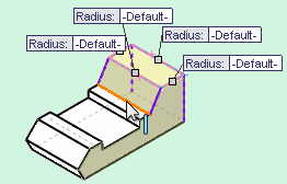
Step 5: Declare bend edges
Under Bend Edges, select the model edges that will form bends.
Change the display style to Hidden Lines Visible to make it easier to select edges.
The rips required are automatically selected and listed under Rip Edges found.
In the graphics area, callouts are attached to the bend and rip edges if you select Show callouts in the PropertyManager. You can use the callouts to change the bend radii and rip gaps.
You can restore the default value by right-clicking the bend edge or rip edge and selecting Restore Default Value.
Step 6: Setting rip options
Under Corner Defaults, set the rip options. To override these defaults by setting options for individual rips:
a. Under Rip Edges found, select Show callouts.
b. In the graphics area, click Default in the gap callout.
c. In the pop-up window, set the rip options.
d. In the graphics area, right-click and click OK ✔️.
Step 7: Bend allowances
Under Custom Bend Allowance, set a Bend Allowance Type and value.
Step 8: Reliefs
To add relief cuts for the inserted bends, under Auto Relief, select the type of relief cut: Rectangular, Tear, or Obround.
Tear reliefs are the minimum size required to insert the bend.
If you select Rectangular or Obround, specify a Relief Ratio.
Step 9: Click ✔️.
Step 10: Flatten
Click Flatten ![]() (Sheet Metal toolbar) to flatten the part using the bends and rips you specified.
(Sheet Metal toolbar) to flatten the part using the bends and rips you specified.