Last updated on August 31st, 2026 at 10:43 am
When forming deep sheet metal boxes, one of the biggest challenges is press brake tooling clearance. A part can look completely valid in CAD but still be difficult or impossible to form if the punch, punch holder, machine, or previously formed walls interfere during the bend sequence.
This becomes especially important with tall flanges, opposing walls, return flanges, and closed box geometries where each bend reduces the amount of space available for the tooling and the part itself.
At Approved Sheet Metal, deep-forming problems are usually solved through a combination of tooling selection, bend-sequence planning, and design-for-manufacturability review.
The deeper or more enclosed the geometry becomes, the more important it is to evaluate whether the tooling can reach the bend without colliding with an already formed wall.
Deep Forming Considerations for Sheet Metal Fabrication
As box depth increases, standard press brake tooling can run out of clearance between the punch, holder, machine, and previously formed features.
At ASM, parts approaching roughly 8" of forming depth typically deserve additional tooling and bend-sequence review, but depth alone does not determine whether a part can be formed. Box width, flange geometry, bend direction, material, thickness, tooling clearance, and the order of operations all matter.
Depending on the geometry, several tooling strategies may help.
Gooseneck Tooling
Gooseneck tooling offsets the punch profile away from the part, creating clearance around previously formed walls and return flanges.
This can allow bends that would otherwise cause the part to collide with a straight punch or punch holder.
Extended-Reach and Gooseneck Punch Holders
Extended-reach or gooseneck punch holders can provide additional clearance when a conventional holder would interfere with a deep wall or enclosed section of the part.
The exact setup depends on the required reach, tooling profile, tonnage, and geometry of the box.
Stacked or Extended Tooling Arrangements
In some applications, stacked or extended tooling arrangements can provide additional reach into deep geometry.
These setups are evaluated based on tooling stability, required forming force, available machine clearance, and whether the part can still be positioned and removed safely throughout the bend sequence.
Acute-Angle Tooling and Multi-Step Bending
Acute-angle tooling can sometimes provide additional clearance during intermediate forming operations.
Rather than forming every flange directly to its final angle in one operation, a part may be partially formed and then brought to its final geometry in a later bend. Whether this approach works depends on the specific part and bend sequence.
Why Bend Sequence Matters in Deep Boxes
Deep boxes often become difficult to form because the part gradually closes around the tooling.
The first bends may be straightforward, while a later bend causes a previously formed wall to collide with the punch, holder, or machine before the required angle can be reached.
Common problem geometries include:
- Tall opposing flanges
- Narrow U-shaped channels
- Deep four-sided boxes
- Return flanges
- Back bends
- Internal features located close to bend lines
- Hardware located near forming areas
- Geometries that leave no clear path to remove the part from the tooling
This is why forming feasibility cannot be determined by box depth alone.
What If the Box Is Too Deep to Form as One Piece?
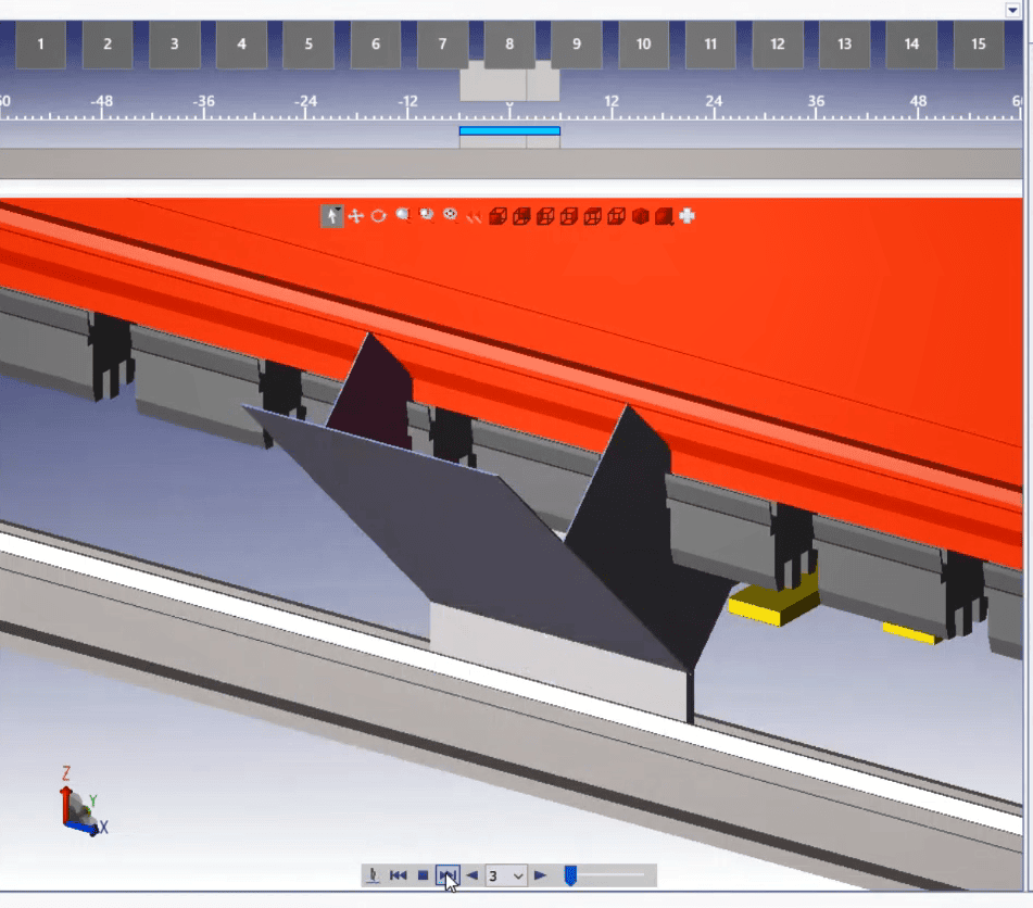
If tooling clearance makes a one-piece design impractical, the enclosure can sometimes be redesigned as two or more manufacturable components.
When evaluating where to split the part, we consider:
- The shortest practical weld or fastening joint
- Structural requirements
- Cosmetic requirements
- Weld access
- Potential weld distortion
- Inspection requirements
- Finishing requirements
- Ease of assembly
ASM can then review the proposed split with the customer before manufacturing.
The components can be joined using welding or mechanical fastening, depending on the functional and cosmetic requirements of the assembly.
For welded designs, seam location should also account for heat input and the possibility of distortion during sheet metal welding.
Springback and Dimensional Accuracy in Deep Forming
All bent sheet metal experiences some amount of springback after the forming force is removed.
Springback is influenced by factors including:
- Material
- Material temper or condition
- Sheet thickness
- Bend radius
- Tooling
- Bend method
- Bend angle
- Grain direction where applicable
Materials such as stainless steel and 6061-T6 aluminum can behave differently from more formable materials, so tooling and bend strategy should be selected accordingly.
Deep geometry does not automatically create more springback, but multiple bends and restricted tooling access can make dimensional variation harder to manage across the completed part.
Critical dimensions should be verified during setup and inspection. If a formal First Article Inspection is required, identify that requirement on the RFQ or purchase order.
Accumulated Variation Across Multiple Bends
Each bend can introduce variation in angle and flange position. In a deep box with several dependent bends, those variations can accumulate at the final opening, lid interface, overall width, or overall height.
Welding multiple formed sections together can introduce additional dimensional variation through fit-up and heat distortion.
To help control critical dimensions, we consider:
- Bend sequence
- Tooling selection
- Datum strategy
- In-process inspection
- Critical-to-function dimensions
- Assembly and welding sequence where applicable
How Engineers Should Tolerance Deep Formed Parts
Deep sheet metal parts should not be given one universal tolerance simply because they fall into the same general category.
Achievable dimensional control depends on the material, sheet thickness, bend radius, number of bends, tooling access, geometry, welding, and which dimensions are functionally important.
When creating the drawing:
- Apply tight tolerances only where they are functionally required
- Clearly identify critical mating dimensions
- Use a logical datum structure
- Identify surfaces that control fit, sealing, or alignment
- Allow reasonable clearance between mating formed parts where the design permits
- Consider whether dimensions should be controlled from a common datum rather than chained across several bends
Factors That Affect Deep-Form Tolerances
| Factor | Why It Matters |
|---|---|
| Material and Temper | Affect springback, ductility, and forming behavior. |
| Sheet Thickness | Affects required tooling, forming force, bend response, and minimum feature geometry. |
| Bend Radius | Affects developed geometry, material strain, and springback. |
| Box Depth | Can reduce tooling access and make inspection or measurement more difficult. |
| Bend Sequence | Determines which bends remain accessible and where dimensional variation accumulates. |
| Number of Bends | More dependent bends can increase tolerance stack-up across the finished part. |
| Welding | Can introduce heat distortion when the box is fabricated from multiple pieces. |
| Finishing | Coating or plating may affect critical mating dimensions and assembly clearances. |
Deep Forming Design Checklist
Before releasing a deep box or enclosure for fabrication, review:
- Can the tooling reach every bend?
- Will an already formed wall collide with the punch or holder?
- Can the part be rotated and removed from the tooling after each operation?
- Are there return flanges or back bends that close off tool access?
- Are holes, hardware, louvers, or other features too close to bend areas?
- Could a flange direction or bend sequence be changed to improve access?
- Would splitting the enclosure into multiple parts simplify forming?
- Are the tightest tolerances limited to dimensions that actually control function?
- If the box will be welded, has potential weld distortion been considered?
Send the Complete 3D Model for Deep-Forming Review
Deep-form feasibility is difficult to evaluate from a few overall dimensions alone.
The 3D model allows our team to evaluate wall height, opposing flanges, return geometry, tool access, bend sequence, and potential collision points before the job reaches the press brake.
A fully dimensioned 2D drawing should also identify material, thickness, critical dimensions, bend requirements, finish, and any inspection requirements.
If a design cannot be formed efficiently as modeled, ASM can review practical alternatives such as changing the bend sequence, modifying a flange, relocating a seam, or fabricating the enclosure as multiple pieces.
Request a quote for your next deep-formed sheet metal part or enclosure.
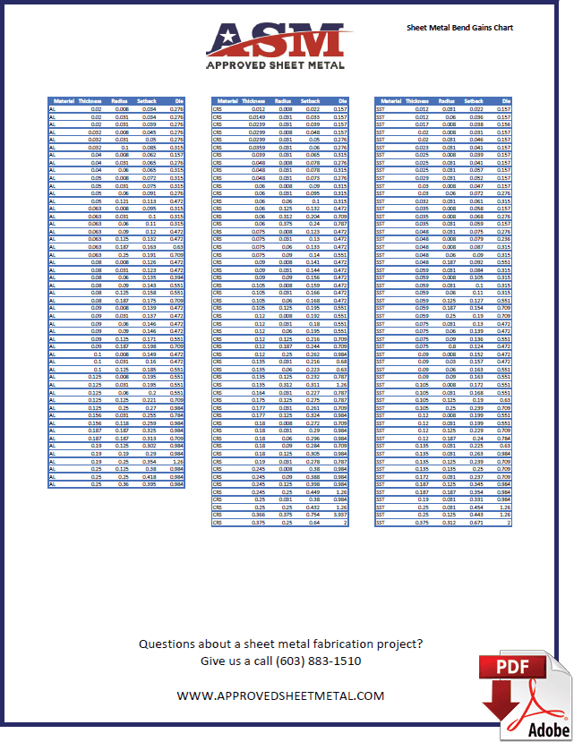
Sheet Metal Bend Gains Chart
BEND GAINS CHART DOWNLOAD
Don’t settle for K factor .5, use these specific bend gains so your manufacturer can use your native CAD model without them wasting time by having to recreate a flat pattern of your sheet metal fabricated parts.