Last updated on January 26th, 2026 at 02:24 pm
In custom sheet metal fabrication, a flange is a bent feature that extends from a primary face. Flanges add stiffness, improve edge quality, and support assembly.
Although flange design appears straightforward, short flange heights are one of the most common causes of forming issues. Designs with insufficient flange length often cannot be formed reliably using standard press brake tooling.
Table of Contents
- 1 Why Minimum Flange Height Is Critical
- 2 Why Flange Height Matters
- 3 Sheet Metal Part Design for Manufacturing Tip
- 4 Sheet Metal Fabrication Flange Formula FAQ
- 4.0.1 What is a flange in custom sheet metal fabrication, and why does flange height matter?
- 4.0.2 How can I ensure the correct flange height in my sheet metal design?
- 4.0.3 Why is the bend radius important in determining flange height?
- 4.0.4 What if I need flanges shorter than the minimum acceptable flange height?
- 4.0.5 How can Approved Sheet Metal help me with my sheet metal design challenges?
Why Minimum Flange Height Is Critical
Flange height determines whether a part can be formed consistently on a press brake. If the flange is too short, the material cannot seat properly in the die, leading to slippage, inconsistent angles, or failed bends. Understanding minimum flange height requirements early helps avoid redesigns and production delays.
Why Flange Height Matters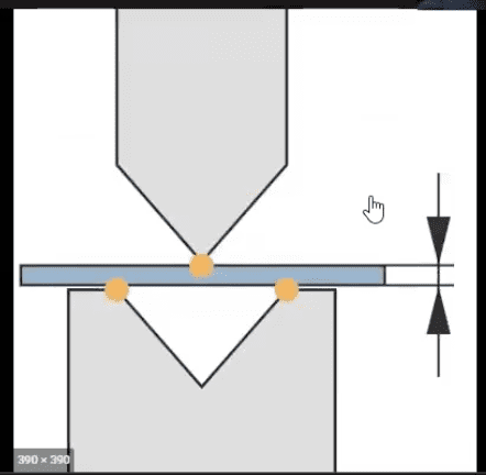
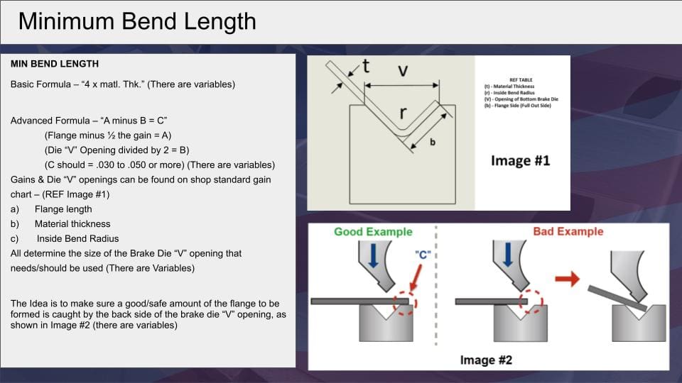
At Approved Sheet Metal, we bend flanges using a v-shaped die on our press brake machines. We lay the material across the die, ensuring that there is ample material on both sides to provide resistance when the press comes down. As the press bends the material into shape, it creates three touchpoints: on the right, left, and center-bottom, forming a "v."
If the flange height is too short, there won't be sufficient material to lay all the way across the v-shaped die. The material will slip out of position when pressed, compromising the flange.
Often, customers are unaware that their designs include insufficient flange heights. While our team of expert engineers is always here to help you assess your designs for manufacturability, we also want to make flange design easier so that you can avoid unneeded back-and-forth with your sheet metal shop.
The Perfect Fit Flange Formula
To ensure your precision sheet metal fabricator can make your parts correctly, we developed a formula that guarantees flanges will always be the right height.
4x Material Thickness + Bend Radius = Minimum Acceptable Flange Height
Pro tip: Jot that formula down or bookmark this blog post so you can return to it for future reference!
Now, let's get into why this formula works.
- Die measurements. We derived this formula from the equation we use to identify the correct die measurements: a die must be 6x the material thickness to work. So, we considered that half of that (3x) plus the bend radius would make the flange height just right. Except, just right doesn't allow for any buffer. If unforeseen issues occur, such as slippage in the machine, we might not have enough material to bend the flange. Plugging 4x the material thickness into the formula ensures we'll have enough height to manufacture a flange correctly and consistently.
- Material thickness. The formula accounts for enough room to make the bend no matter what material is used. The thicker the material, the wider the die must be to hit each of the three critical contact points.
- Bend radii best practices. Bend radius is an equally important metric when identifying flange height. Your best bet when designing formed parts is to use the industry standard bend radius of 0.030". We use 0.030" for all material thicknesses up to 0.125" (⅛") and increase the bend radius for thicker materials.
A Solution for Shorter Flanges
Sometimes, customers need flanges shorter than the minimal acceptable flange height. If you know Approved Sheet Metal, you know we strive to find solutions to meet all of our customers' needs.
When our customers need shorter flanges, we'll start by using the same formula to create a longer flange, then use an end mill to cut the flange down to meet their specs. While this alternative is a functional option and can work for low-volume or prototype orders, it's not ideal for production work due to the multiple setups required for each part.
Cutting off a significant amount of material can also cause the material to bow, compromising part structure. And, frankly, it leads to unnecessary and expensive material waste. If you want to save time and money, avoid making your flange height too short in the first place.
Remember—you don't have to do this work alone! We’re always happy to help you update your design. Our team has decades of experience in fabrication, and we can make recommendations and adjustments that simplify the manufacturing process and get you the parts you need.
Material Specific Guidelines
Material properties directly affect bend behavior, minimum flange height, and the placement of features near bends.
1. Material Thickness and Bend Radius
- General Rule: The inside bend radius should be at least equal to the material thickness to prevent cracking and ensure proper forming.
- Aluminum: Due to its lower ductility compared to steel, aluminum requires a larger bend radius to prevent cracking. A common practice is to use a bend radius equal to 1.5 times the material thickness.
- Stainless Steel: Stainless steel's higher strength necessitates careful consideration of bend radius. A minimum bend radius equal to the material thickness is typically recommended, but increasing the radius can reduce the risk of cracking.
2. Minimum Flange Length
- Guideline: The minimum flange length should be at least four times the material thickness.
- Application: This guideline helps in achieving accurate bends and maintaining part strength across different materials.
3. Hole and Slot Dimensions
- Soft Materials (e.g., Aluminum): The minimum hole diameter should be equal to the material thickness to prevent tool damage and ensure clean cuts.
- Hard Materials (e.g., Stainless Steel): The minimum hole diameter should be twice the material thickness to account for increased material strength and reduce the risk of deformation.
4. Distance from Features to Bend Edges
- Holes and Slots: Maintain a minimum distance from the edge of a hole or slot to a bend equal to three times the material thickness plus the bend radius. This prevents distortion during bending.
- Notches and Tabs: Notches should be at least the material thickness in width and no longer than five times their width. Tabs should be at least twice the material thickness and no longer than five times their width.
5. Material Selection Impact
- Aluminum: Lightweight and corrosion-resistant but less ductile, requiring careful consideration of bend radii to prevent cracking.
- Stainless Steel: Offers excellent strength and corrosion resistance but has higher hardness, necessitating larger hole sizes and increased tool wear considerations.
- Cold Rolled Steel: Provides good ductility and is cost-effective, suitable for a variety of applications with standard bend radii.
Designing flanges with proper height reduces risk, shortens lead time, and improves part consistency. If you are unsure whether your flange dimensions meet forming requirements, our team can review your design and recommend adjustments before fabrication begins.
Sheet Metal Part Design for Manufacturing Tip
BENDS
Bending sheet metal parts is a process that is completed by utilizing press brakes and our very skilled press brake operators. At Approved Sheet Metal, we can hold tolerances of +/- 1 degree on most bend angles. The ideal bend radius on formed parts is 0.030 in., this ensures that you can get consistent, quality parts that will maintain solid structural integrity.