Last updated on February 3rd, 2025 at 12:53 pm
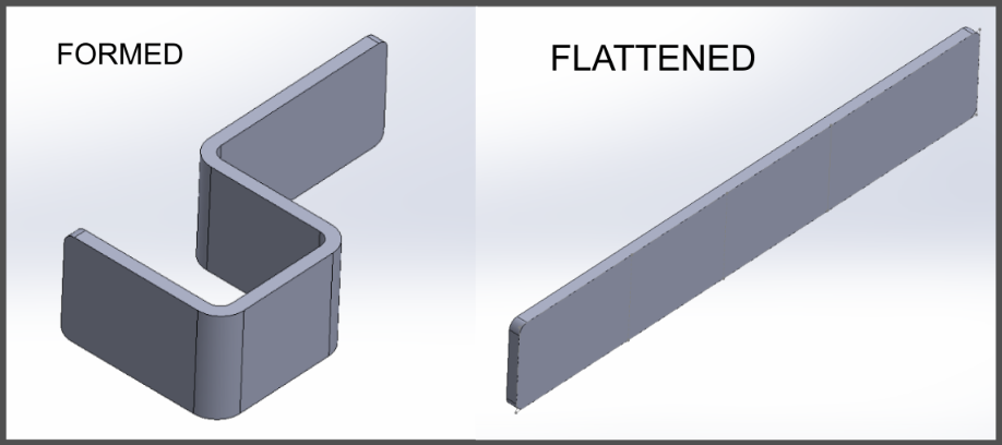
Before we can fabricate your sheet metal part, the solid 3D design file must be converted to a flat part file. Ensuring that your part flattens is crucial for avoiding common issues such as:
- Crashing bends
- Missing bend reliefs
- Missing flanges
Here, we’ll review how to go from 3D model to flat sheet metal and outline the eight design tips you should follow to create 3D models that unfold.
Table of Contents
- 1 Getting from 3D Model to Flat Sheet Metal in Sheet Metal Fabrication
- 2 8 Design Tips for Making 3D Models That Unfold
- 2.1 1. Use the “Convert to Sheet Metal” command
- 2.2 2. Design with uniform thickness
- 2.3 3. Review your surface imports
- 2.4 4. Verify the seams
- 2.5 5. Calculate the correct bend radii
- 2.6 6. Design bend reliefs beside each bend feature
- 2.7 7. Avoid crashing features
- 2.8 8. Carefully select your part’s feature locations
- 3 A note on K-Factor
- 4 Get Custom Metal Fabrication Services at Approved Sheet Metal
- 5 Sheet Metal Design for Manufacturing
- 6 Convert Solid 3D Designs to Flat Sheet Metal FAQ
- 6.0.1 Why is it crucial for a 3D design file to flatten properly before sheet metal fabrication?
- 6.0.2 What are the common complications in sheet metal design when engineers overlook unfolding their 3D models?
- 6.0.3 How can SOLIDWORKS users flatten and unfold 3D models for sheet metal fabrication?
- 6.0.4 Can you provide an example of how unfolding a design impacts fabrication decisions?
- 6.0.5 Why is it essential for customers to ensure their designs unfold properly before requesting a quote?
Getting from 3D Model to Flat Sheet Metal in Sheet Metal Fabrication
As you’re probably aware, you should always begin by designing your parts as 3D models. Sure, it sounds counterintuitive, but have you ever tried designing a bend into a flat model? If so, then you’re already familiar with the resulting complications.
The problem is that oftentimes we see engineers don’t take the step to unfold their 3D models. Many designers simply don’t know how to do it because they were never taught sheet metal fabrication techniques to the same degree as they were taught CNC machining techniques.
But here’s the thing: about 60% of the part designs we receive at the Approved Sheet Metal shop arrive with issues that unfolding the 3D model would have easily resolved. This presents a lot of opportunity to share knowledge and decrease lead time and cost associated with managing part files.
Since SOLIDWORKS is our customers’ preferred CAD software, here’s a quick primer on flattening and unfolding a 3D model in SOLIDWORKS:
How to locate the Sheet Metal toolbar:
- Navigate to Command Manager
- Choose Sheet Metal from the dropdown list
How to create a sheet metal tab:
- Create or choose a plane or planar face
- Sketch the tab on the plane to define its size
- Select Base Flange/Tab on the Sheet Metal toolbar
or
- Click Insert > Sheet Metal > Base Flange
- Create a tab from your sketch using the standard sheet metal thickness, or select the tab and click Edit Sketch to alter any of its dimensions
How to unfold your design:
Unfolding your sheet metal design can be very revealing! In fact, we recently declined a part because, after unfolding the design, we saw that it was way too big for our shop’s machinery. Had we neglected to unfold the part before proceeding, we could have wasted significant time moving forward with an impossible part.
Before you request a quote, use one of three simple methods to unfold your design.
- Option 1. Right-click the part and select Flatten from the Sheet Metal toolbar to unfold it > Click Exit Flatten to refold the part
- Option 2. Navigate to the Cut List > Select your part > Click Process Bends > Select Flatten > Click Exit Flatten to refold the part
- Option 3. Navigate to the Sheet Metal toolbar > Select Flatten > Click Flatten again to refold the part
SOLIDWORKS Tech Tip #3: Unable to Unfold Part, Sheet Metal Bend Radius Issue Solved
8 Design Tips for Making 3D Models That Unfold
So you’ve designed a formed part and used an Unfold command to preview the part’s functionality, but—uh-oh!—the unfolding doesn’t proceed as intended. Now what?
We’ve compiled eight design tips to help you create custom metal fabrication designs that unfold successfully. Incorporate these considerations into your workflow, and you’ll soon be on track to achieve high-quality, cost-efficient, quick-turnaround parts.
1. Use the “Convert to Sheet Metal” command
You should always begin your sheet metal design from the Sheet Metal toolbar. This approach enables SOLIDWORKS to flag potential errors and saves “future you” a great deal of frustration!
If you’ve already created a solid 3D model, however, you can use the software’s Convert to Sheet Metal option to adapt the design for sheet metal fabrication. (Beware that this process isn’t always perfect since some flat parts are incredibly complex!)
2. Design with uniform thickness
It’s easy to forget that sheet metal parts must be designed with uniform thickness! For example, if your sheet is 10-gauge aluminum at 2.588 mm thick, your entire part must be designed with the same thickness.
3. Review your surface imports
However counterintuitive it may be, SOLIDWORKS will allow you to design a part that’s all surfaces with no material thickness. But even a flat part has a thickness measurement! For example, if you form a 90-degree bend in sheet metal, the part will have 10 surfaces: four flat sides plus six edges.
Take a look at your toolbar’s surface imports tree. If you see a thickness of zero, your part won’t unfold correctly. You can prevent this problem by starting your design with a solid body and uniform thickness.
4. Verify the seams
Seams are necessary for many formed sheet metal parts, as they dictate where the material will unfold.
If you’re using the Convert to Sheet Metal command, SOLIDWORKS will add seams automatically; double-check that they’re precisely where you need them!
Also, remember to note in your design whether the seams should be welded closed after forming.
5. Calculate the correct bend radii
Use this formula to determine your part’s external bend radius:
Internal Radius + Material Thickness = External Bend Radius
Remember that there’s no such thing as a perfectly sharp right angle in sheet metal fabrication. Bending leaves at least a subtle curve at each bend point. These internal and external curves are called “bend radii.” Call out your part’s bend radii to avoid any delays or confusion at the sheet metal shop.
6. Design bend reliefs beside each bend feature
Because the bending process stretches the sheet metal, you must design bend reliefs on either side of any bend feature to prevent pulling or tearing. Bend reliefs are simply small incisions that allow a flange, for example, to move without warping the surrounding material.
Yes, bend reliefs do leave tiny holes at each corner, but our sheet metal shop can easily strengthen these corners with welding if necessary.
7. Avoid crashing features
Imagine you’ve designed your sheet metal part with a square hole at the center and four flanges bent outward from that hole, each the same size as the hole. Obviously, only one of those flanges can come from the hole’s material, right? Yet many part designs incorporate “crashing features”—such as a hole with four equally sized flanges that could only have come from the Twilight Zone.
Prevent these crashing features by designing an additional part or parts that will form the box surrounding the hole.
8. Carefully select your part’s feature locations
Aesthetics aren’t the only consideration when designing your part’s features. It’s imperative that you follow a few basic formulas to avoid warping and deformation during the forming process.
- 4 x Material Thickness = Hole Distance from Bend
- 4 x Material Thickness = Flange Length
- 4 x Material Thickness = Hem Length
A note on K-Factor
When designing sheet metal parts, accurately predicting how the material bends is crucial for ensuring a successful flat pattern. The K-factor is a fundamental concept that helps determine the amount of material stretching during bending, directly affecting the unfolded part’s accuracy.
What Is K-Factor?
The K-factor is a ratio that represents how much of the material’s thickness remains neutral (unchanged in length) during bending. It is calculated as:
K = Neutral Axis Distance from Inner Surface /
This value typically ranges from 0.3 to 0.5, depending on material type and bend radius. A lower K-factor means more material compression, while a higher K-factor indicates more stretching.
Why Is K-Factor Important?
The K-factor directly affects:
- Flat Pattern Accuracy: If the K-factor is incorrect, the unfolded part will have incorrect dimensions, leading to misaligned holes, improper fit, or scrap.
- Bend Allowance and Bend Deduction: These values are used to determine how much material is added or removed at bends to maintain correct dimensions.
- Consistency in Production: Using the right K-factor ensures that all parts bend consistently, reducing manufacturing errors and rework.
How to Determine the Correct K-Factor
- Use Manufacturer-Supplied Values: Many sheet metal suppliers provide recommended K-factors based on material type and thickness.
- Refer to Standardized Charts: Industry-standard charts list K-factors for common materials and bend radii.
- Perform Physical Testing: If precise accuracy is required, bending a test piece and measuring the results is the most reliable method.
- Use SOLIDWORKS Bend Tables: SOLIDWORKS allows you to input custom bend tables with accurate K-factors for different materials and thicknesses.
Typical K-Factor Ranges
| Material | K-Factor (Typical) |
|---|---|
| Aluminum (0.063" thick) | 0.33 – 0.40 |
| Mild Steel (0.125" thick) | 0.35 – 0.45 |
| Stainless Steel (0.060" thick) | 0.30 – 0.40 |
By correctly setting the K-factor in your CAD software, you can avoid costly mistakes, ensure manufacturability, and produce parts with accurate dimensions. If you’re unsure which K-factor to use, our team at Approved Sheet Metal can help determine the best value based on your specific design and material.
Get Custom Metal Fabrication Services at Approved Sheet Metal
The pros at our sheet metal shop have the DFM and SOLIDWORKS knowledge you need to ensure exceptional quality. If you have questions about using SOLIDWORKS for sheet metal design or want to verify the manufacturability of your part, we encourage you to reach out to our experienced team of engineering professionals. You can also make the most of our expertise by taking advantage of our SOLIDWORKS Resource Page and Sheet Metal DFM eBook! We’re constantly updating our Resource Page with new information to help you better understand the fundamentals of sheet metal design.
Ready to move forward with your project? Go ahead and request a quote!
Sheet Metal Design for Manufacturing
FREE eBOOK DOWNLOAD
Design parts with the sheet metal fabrication process in mind. Reduce cost and get parts on your desk faster! Learn about the following best practices when designing sheet metal parts:
- Hems & Offsets
- Notches & Tabs
- Corners & Welding
- Uniform Thickness and more!
")