Last updated on February 4th, 2026 at 01:02 pm
Part designers have one goal: to produce a Class A prototype in the shortest amount of time possible. As sheet metal fabricators, we use the phrase “another day, another thousand dollars.” The longer your part takes on the shop floor, the more time and money are spent on set up, machining, and reworking.
To avoid racking up a hefty sum on your invoice, the key is to make your design as close to the end product as possible. What should you be watching out for in your sheet metal design file? Here’s our list—make sure to check it twice. 😉
Table of Contents
- 1 Top 5 Things to Check in Your Sheet Metal Design File
- 2 File Format & Data Integrity Tips
- 3 Recommended Default Sheet Metal Tolerances
- 4 Sheet Metal Design File FAQ
- 4.0.1 Why is it important to check the material thickness in my sheet metal design file?
- 4.0.2 What is tolerance, and why should I consider it in my sheet metal design?
- 4.0.3 Should I customize inside radii in my sheet metal design?
- 4.0.4 Why is it recommended to leave some wiggle room in overlapping parts of a design?
- 4.0.5 How can I avoid complications related to welding in my sheet metal design?
Top 5 Things to Check in Your Sheet Metal Design File
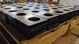
- Material thickness. Not all manufacturers carry standard material gauges in their shops, and suppliers can take 3-4 days to fulfill an order for a specific material thickness. If your prototype is modeled at a material thickness that is nonstandard (or doesn’t even exist!), you could waste time looking for material or redoing your design to match what’s available. Do yourself a favor and ask your manufacturer what materials they carry before you start sketching.
- Tolerance. Powder-coating or painting your part? Include additional tolerance for the finishing layer. It pays to be precise.
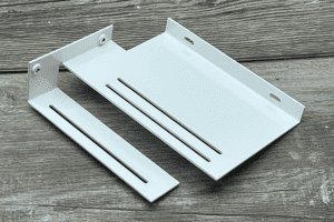
- Inside radius. Most shops use standard tooling to achieve common inside radii. Instead of customizing these dimensions for your design, stick to standard measurements. You’ll make your manufacturer’s life much easier. (Pro tip: Whenever possible, put a maximum radii on your part so tooling won’t be a problem!)
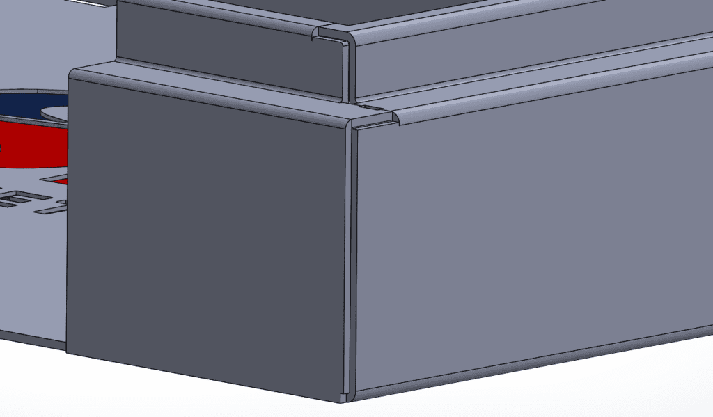
- Overlapping parts. When creating two parts that are designed to fit into each other (e.g. a box with a lid), don’t aim for a snug fit. Life isn’t perfect, so leave a little wiggle room in case you need to accommodate bowing in the material. #wiggleroom
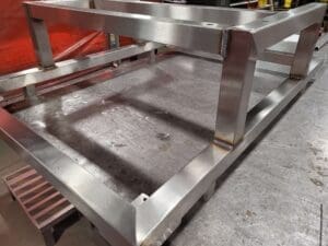
- Welding. Welding can cause complications like material shrinkage and cracking that may affect budget and lead time. The best way to avoid this headache? Tell your manufacturer ahead of time if your part needs to be welded. The same goes for notching and tabbing: inform your manufacturer so they can create a game plan on how to address issues that might arise.
File Format & Data Integrity Tips
Ensuring your design files are accurate and compatible with your sheet metal fabricator’s systems is crucial for a smooth manufacturing process. File format and data integrity issues are common causes of delays, miscommunication, and costly rework. Here’s what you need to know:
Preferred File Formats
- STEP (.step or .stp): The industry standard for 3D CAD file exchange, STEP files maintain solid body geometry and are widely accepted by sheet metal shops. They preserve precise dimensions and features, making them ideal for fabrication programming.
- IGES (.iges or .igs): An older CAD exchange format that can handle surface and solid models but sometimes causes data translation errors. Use with caution, especially for complex sheet metal parts.
- Native CAD Files: Formats like SolidWorks (.sldprt), Autodesk Inventor (.ipt), or Fusion 360 files are preferred if your fabricator uses the same CAD system, as they preserve all model details and metadata.
- Avoid Surface-Only Files: Files containing only surfaces (without a solid body) are problematic because they lack thickness data needed for unfolding and fabrication. Always confirm your model is a solid body before sending.
Ensuring Data Integrity
- Verify Solid Body Geometry: Double-check that your CAD model is a complete solid with no gaps or holes. Use your CAD software’s tools to inspect and repair geometry.
- Include All Features: Make sure all features relevant to manufacturing—like bends, holes, tabs, and weld details—are present in the file. Missing features often require clarifications or adjustments later.
- Simplify Complex Geometry: Where possible, simplify overly complex models by removing unnecessary details that don’t affect function. This reduces file size and processing time without sacrificing accuracy.
- Clean Up Sketches and History: Delete unused sketches, construction geometry, or extraneous components to avoid confusion or errors during fabrication.
- Coordinate with Your Fabricator: Confirm preferred file formats and submission methods before sending your files. Some shops have specific requirements or portals that streamline the upload and review process.
Why This Matters
Incorrect or incomplete files cause programming delays, incorrect part fabrication, and extra communication overhead. By submitting clean, accurate files in the correct format, you help your fabricator hit the floor faster and get your parts made right the first time—saving time, cost, and frustration.
Get your part done faster by checking your sheet metal design file before you submit it to your fabricator. If you’re unsure how your design might affect the manufacturing process, don’t hesitate to give us a call. We’re always happy to share advice from the shop floor.
Need quick turn sheet metal fabrication services? Give us a shot on your next project!
Recommended Default Sheet Metal Tolerances
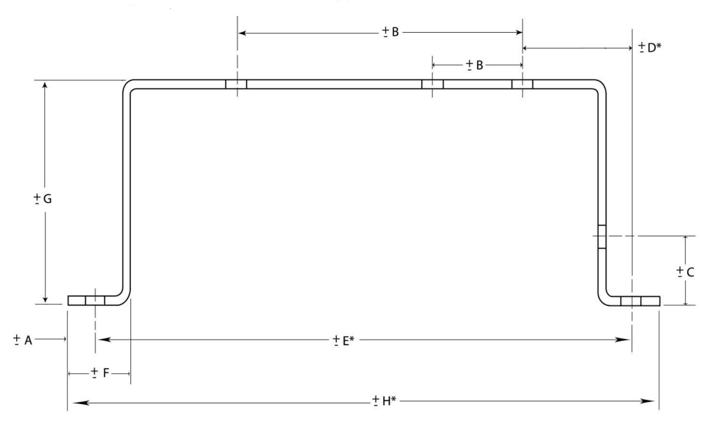
| DIM | Tolerance (MM) | Tolerance (Inches) | Description |
| A | ± 0.13 | ± 0.005 | Sheared Edge to Hole |
| B | ± 0.13 | ± 0.005 | 2 Holes on One Surface |
| C | ± 0.25 | ± 0.010 | Formed Edge to Hole |
| D* | ± 0.76 | ± 0.030 | Holes Across 2 Bends |
| E* | ± 0.76 | ± 0.030 | Holes Across 4 Bends |
| F | ± 0.25 | ± 0.010 | Sheared Edge to Bend |
| G | ± 0.38 | ± 0.015 | Across 2 Bends |
| H* | ± 0.76 | ± 0.030 | Formed Part |
Noted dimensions are to be taken while the part is in a restrained condition. Noted dimensions are for parts within a 12” envelope.
* Dimensions D, E and H are not recommended forms of dimensioning
These tolerances are recommended and best practices. We can obtain tighter tolerances (depending on part geometry/ construction), contact us for more information