Last updated on February 11th, 2026 at 12:59 pm
Are you designing sheet metal parts in SOLIDWORKS? If you have got questions, you are not alone. While many programs provide helpful information for designing precision machined parts with this CAD platform, training regarding how to design sheet metal fabricated parts is far less common.
Here, we share answers to some of the top SOLIDWORKS questions we have encountered as a sheet metal shop. The goal is not just to help you model a part, but to help you model it in a way that fabricates cleanly, quotes faster, and matches the flat pattern your shop will actually run.
How to find the Sheet Metal Toolbar in SOLIDWORKS?
At first glance, the busy SOLIDWORKS interface can feel a bit overwhelming. Finding the appropriate toolbar for sheet metal design will orient you to the features you need for your sheet metal prototype. It also ensures you are building with sheet metal rules from the start, which helps SOLIDWORKS catch manufacturing problems earlier.
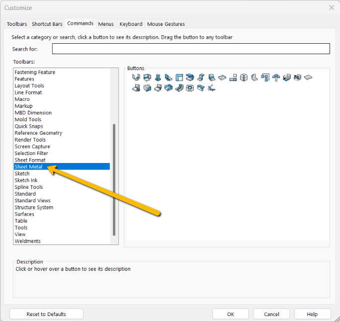
- Navigate to CommandManager.
- Choose Sheet Metal from the dropdown list.
How to Create a Sheet Metal Tab in SOLIDWORKS
Now that you have found the Sheet Metal toolbar, creating a tab is simple. Starting with a base flange also helps establish material thickness, bend radius, and k-factor behavior early, which improves flat pattern reliability as you add more features.
- Create or choose a plane or planar face.
- Sketch the tab on the plane to define its size.
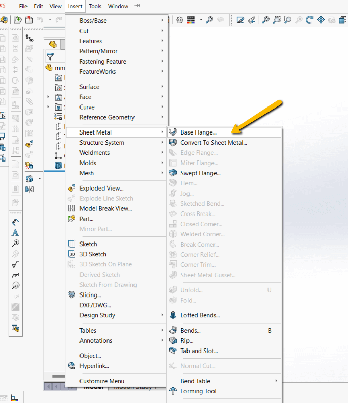
- Select Base Flange/Tab on the Sheet Metal toolbar.
OR
Click Insert → Sheet Metal → Base Flange.
Create a tab from your sketch using the standard sheet metal thickness, or select the tab and click Edit Sketch to alter any of its dimensions. If you change thickness later, always recheck bend radius and flat pattern output to avoid surprises during quoting and forming.
How to Flatten and Unflatten Sheet Metal in SOLIDWORKS
When designing your sheet metal prototype in SOLIDWORKS, it is often useful to toggle between the flat pattern and the formed model. This is not just a visualization step. Flat pattern accuracy impacts whether a shop can run your file as-is or has to recreate the flat before cutting.
There are three ways to flatten and unflatten sheet metal parts in SOLIDWORKS.
- Right-click the part and select Flatten from the Sheet Metal toolbar.
- Navigate to the Cut List, choose your sheet metal part, click Process Bends, and select Flatten.
For both 1 and 2, click Exit Flatten again to refold the part.
- Navigate to the Sheet Metal toolbar and select the Flatten feature.
Click the Flatten feature again to refold the part. If your flat pattern looks incorrect, the cause is often bend radius, k-factor, gauge table selection, or features too close to bends.
How to Fold and Unfold Sheet Metal in SOLIDWORKS
Unfolding and folding are similar to flattening and unflattening in SOLIDWORKS. A flattened part represents what the part will look like before forming. An unfolded part is especially useful when you need to add or review features while the part is temporarily opened up.
If you need a more detailed view, choose Unfold/Fold:
- Click Fold or Unfold from the Sheet Metal toolbar.
OR
- Select Insert → Sheet Metal → Fold/Unfold.
How Do I Find the Minimum Bend Radius?
Sheet metal forming can be a precarious process. To avoid damaging a part during forming, you must take into account material type, thickness, grain direction, and the forming method being used. These factors help you determine the minimum bend radius.
Many customers mistakenly believe their minimum bend radius should equal their material thickness (for example, if the material is 0.125 inches thick, the smallest possible bend radius is 0.125 inches). That requirement applies to only about 15% of the sheet metal prototypes we see. Restricting the bend radius to thickness can also force specialty tooling and increase cost and lead time.
The default bend radius in SOLIDWORKS is often set to 0.100 inches. For many shops, that radius is not a standard tooling match, which can require specialty tooling or additional forming steps. In most common sheet metal work up to 0.125 inch thick, we recommend changing the bend radius to 0.030 inches because it is a widely used inside radius and supports more consistent results across typical press brake tooling.
If you are unsure, the best approach is to match your bend radius to the press brake tooling your shop uses most often. That keeps forming predictable and reduces the chance that a shop has to modify your model before quoting.
To set a bend radius in SOLIDWORKS: 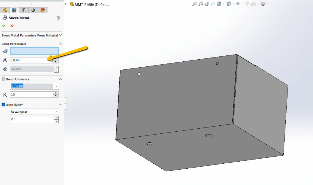
- Navigate to the FeatureTree, select Sheet Metal, and expand the sheet metal feature.
- Click Edit Feature.
- Select the appropriate gauge table from the Sheet Metal Gauges list.
- Select the appropriate edge or face for your bend.
- Set the bend radius.
What Is the K-Factor in Sheet Metal Design?
The k-factor, the ratio that defines the neutral axis location through the thickness of the material, controls how SOLIDWORKS calculates stretch in a bend. That directly affects flat pattern accuracy. If the k-factor is wrong, the flat pattern can be wrong, and that often creates quoting delays or shop revisions.
Choosing an accurate k-factor in SOLIDWORKS, rather than relying on a generic default such as 0.5, helps a sheet metal shop save time by enabling them to use your native CAD model and flat pattern with confidence. Otherwise, the shop may need to recreate a flat pattern or adjust bend allowances to ensure formed dimensions match the drawing. Accurate k-factor values also support more consistent bends when dimensions are sensitive.
Download our FREE sheet metal bend gains chart to determine your K factor.
To set a k-factor in SOLIDWORKS: 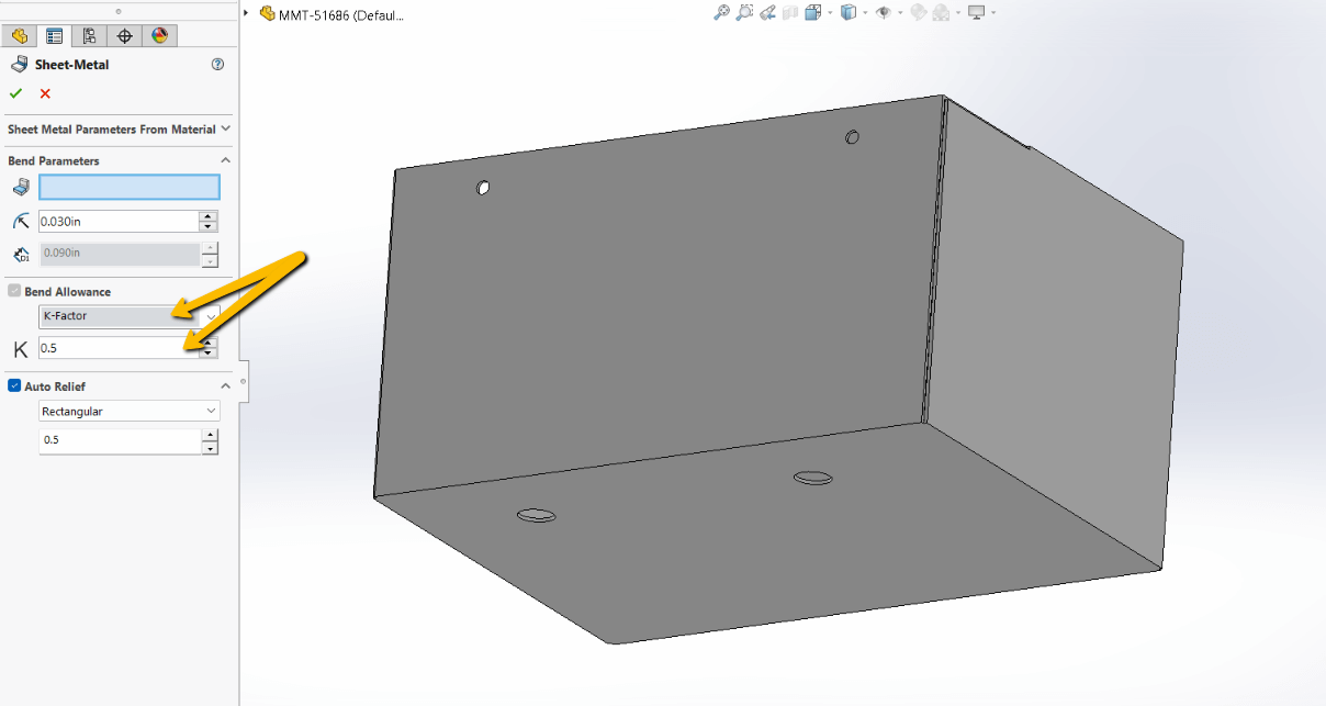
- Navigate to the FeatureTree, select Sheet Metal, and expand the sheet metal feature.
- Click Edit Feature.
- Select the appropriate gauge table from the Sheet Metal Gauges list.
- Select the appropriate edge or face for your bend.
- Set the k-factor.
Sheet Metal Part Design for Manufacturing Tip
BENDS
Bending sheet metal parts is a process that is completed by utilizing press brakes and our very skilled press brake operators. At Approved Sheet Metal, we can hold tolerances of +/- 1 degree on most bend angles. The ideal bend radius on formed parts is 0.030 in., this ensures that you can get consistent, quality parts that will maintain solid structural integrity.

 Should I Convert to Sheet Metal or Design a Sheet Metal Part?
 Should I Convert to Sheet Metal or Design a Sheet Metal Part?
While SOLIDWORKS does have functionality to convert a solid part into a sheet metal design, we recommend designing as sheet metal from the outset by creating your part from the Sheet Metal toolbar. This approach helps SOLIDWORKS flag issues earlier, including problems that may appear when folding, unfolding, or generating a flat pattern.
Converting a solid can work in some cases, but it often creates extra cleanup, especially when the model contains features that do not translate cleanly into sheet metal rules. If your goal is faster quoting and fewer revisions, starting in sheet metal is usually the more reliable path.
Sheet Metal Modeling in SOLIDWORKS That Improves Manufacturability
The following guidance is based on the issues we see most often when customers submit SOLIDWORKS models for fabrication. These are the choices that most frequently affect cost, lead time, and whether a shop can run your files without rebuilding them.
1. Best Practices for Sheet Metal Modeling in SOLIDWORKS
- Utilize the Sheet Metal Module: Begin designs with the dedicated sheet metal tools in SOLIDWORKS so thickness, bend radius, and flat pattern behavior are controlled by sheet metal rules.
- Maintain Consistent Material Thickness: Ensure uniform thickness throughout the design. Thickness changes often force a shop to remodel features or split the part into multiple components.
- Apply bends early and verify the flat: Apply bend features early so you can validate bend behavior and flat pattern output before adding complex cutouts, embosses, or hardware features.
2. Common Mistakes to Avoid in Sheet Metal Design
- Placing features too close to bend lines: Holes, cutouts, and tabs too close to bends can distort during forming. A common guideline is to keep features at least four times material thickness away from bend lines when possible.
- Incorrect bend radius specifications: Specifying non-standard radii can trigger special tooling or additional setups. Use appropriate bend radii to improve consistency and reduce cost.
- Overlooking material and bending constraints: Different materials form differently. Ignoring bend direction, grain direction, or minimum radius behavior can lead to cracking, distortion, or a redesign request.
3. Advanced Features in SOLIDWORKS for Sheet Metal Design
- Using the Convert to Sheet Metal Tool: Convert can be useful for certain geometries, but always validate the resulting flat pattern and confirm bend parameters are realistic for fabrication.
- Implementing Weldments for Structural Designs: Weldments can help when assemblies require welded structural parts and fixtures, but sheet metal should still be modeled using sheet metal rules where applicable.
- Simulation and Analysis: SOLIDWORKS simulation tools can help validate sheet metal designs under load, but manufacturability still depends on bend rules, tooling constraints, and feature placement.
What to Send Your Sheet Metal Shop to Speed Up Quoting
If you want the fastest quote turnaround with the fewest revisions, send both the formed model and flat pattern information. Most RFQ delays happen when a shop has to recreate a flat pattern or clarify missing fabrication-critical assumptions such as thickness, bend radius, or bend allowance behavior.
Looking for a sheet metal shop with DFM expertise and an in-depth understanding of SOLIDWORKS? Take a look at our SOLIDWORKS Resource Page and our Sheet Metal DFM eBook.