
Last updated on September 3rd, 2026 at 09:45 am
Before you submit your quote request, include a 3D CAD model and a dimensioned drawing whenever possible.
For custom sheet metal fabrication, these two files serve different purposes. The 3D model communicates the part geometry, while the drawing communicates requirements such as tolerances, material, finish, hardware, welding, inspection, and other manufacturing notes.
Approved Sheet Metal requires a 3D model at the time of order. If one is not available, additional charges and lead time may be required to create the model before manufacturing.
Why 3D CAD Models Matter in Sheet Metal Fabrication
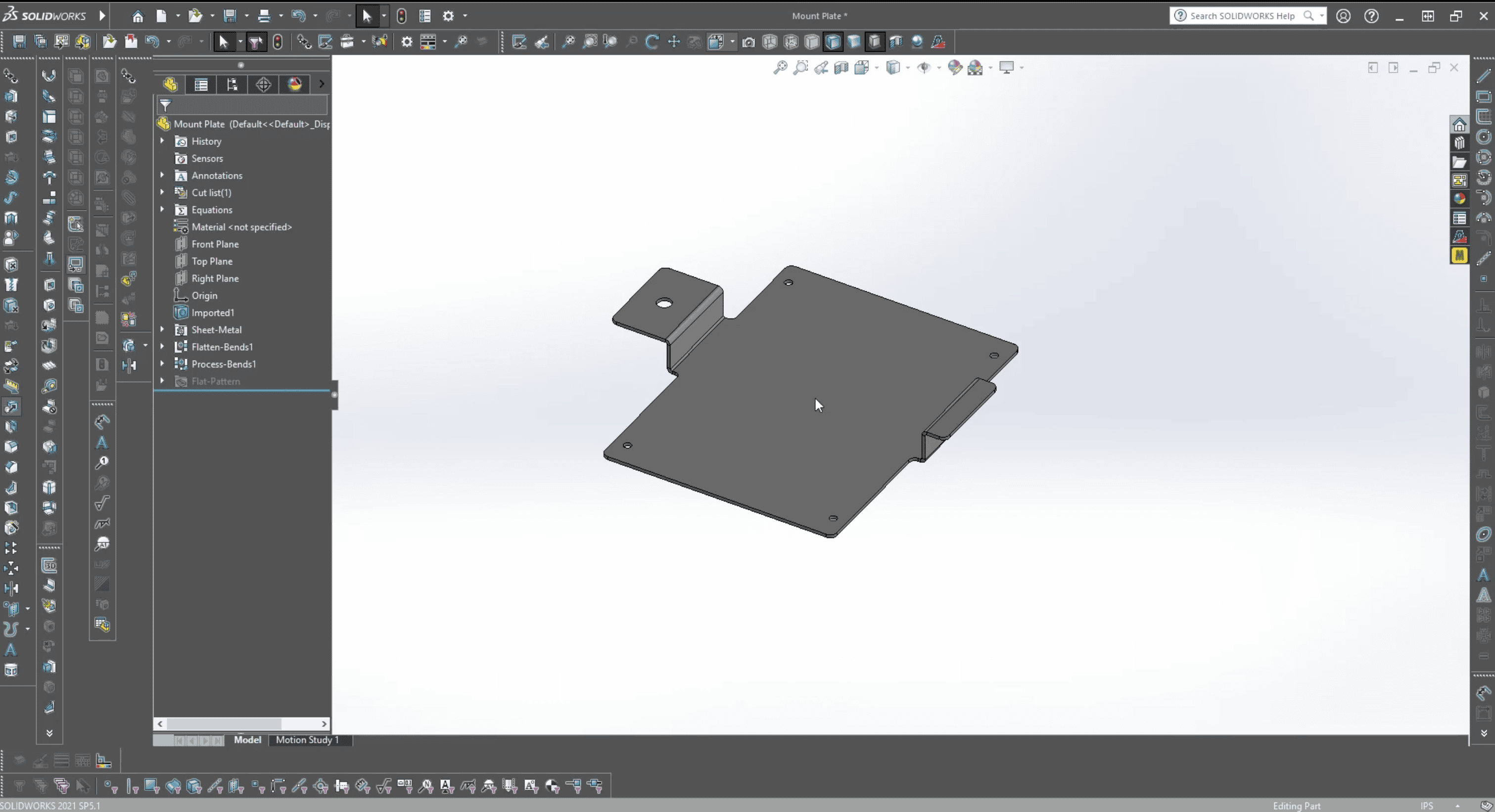
Our quoting team regularly receives RFQs that include a drawing but no 3D CAD model.
A complete drawing can communicate a significant amount of manufacturing information, but recreating a complex formed part from a 2D drawing is less efficient than working from the original 3D geometry.
A usable CAD model gives our estimating and manufacturing teams a much clearer representation of the part, including bends, holes, cutouts, formed features, and the relationships between those features.
3D Model vs. 2D Drawing: Why You Usually Need Both
The 3D model and drawing should work together rather than replace one another.
| 3D CAD Model | 2D Drawing |
|---|---|
| Overall part geometry | Material and thickness |
| Bends and bend direction | Dimensional tolerances |
| Hole, slot, and cutout geometry | GD&T requirements |
| Formed features | Finish specifications |
| Feature relationships | Hardware requirements |
| Assembly geometry | Weld requirements |
| Interference and clearance review | Inspection and documentation requirements |
| Manufacturability review | Cosmetic and workmanship notes |
For example, a CAD model may clearly show the location and geometry of a self-clinching fastener hole, while the drawing identifies the exact hardware manufacturer and part number that must be installed.
Similarly, a model can communicate the geometry of a welded enclosure, but the drawing may define which seams are welded, cosmetic weld requirements, finish requirements, and critical dimensions after welding.
How a 3D CAD Model Improves the Quoting Process
A usable 3D model allows quoting software and estimators to evaluate part geometry much more efficiently than manually recreating the part from a drawing.
Faster Geometry Review
With the model available, our team can evaluate overall dimensions, bends, cutouts, holes, formed features, and other geometry directly from the digital part.
Without a model, additional manual interpretation or CAD work may be necessary before the job can be accurately evaluated.
Less Manual Data Entry
Using model geometry reduces manual transcription and gives the estimating team a more complete digital representation of the part.
That does not mean the CAD model should be accepted without review. Models can contain incorrect geometry, outdated revisions, suppressed features, or information that conflicts with the drawing.
The value is that the fabricator starts with the customer's actual 3D geometry rather than attempting to reconstruct it from dimensions on a print.
Better DFM Review
A 3D model also helps us identify potential manufacturing concerns before production.
During design review, we can evaluate conditions such as:
- Bend accessibility
- Deep or restrictive formed geometry
- Return flanges and back bends
- Features located close to bends
- Hardware near formed features
- Small or difficult cut geometry
- Special punched or formed features
- Potential tooling interference
- Weld access
- Assembly clearance
If we identify a manufacturing concern, we can make Design for Manufacturing recommendations before those issues affect production.
How CAD Models Are Used During Cutting and Forming
A supplied 3D model is not simply unfolded and sent directly to a laser without review.
For a formed part, the model gives our team the geometry needed to evaluate the finished part, develop or verify the flat pattern, review bend conditions, and prepare the part for cutting and forming.
Depending on the model and manufacturing process, the fabricator may need to:
- Convert geometry into a usable sheet metal model
- Verify material thickness
- Review bend radii
- Adjust bend parameters
- Develop or modify the flat pattern
- Review bend reliefs
- Confirm tooling access
- Determine bend sequence
- Prepare cutting and forming programs
This is one reason the finished 3D model is more important than a customer-generated flat pattern for many formed parts.
The manufacturing flat may need to reflect the material, tooling, and bend data used by the fabricator.
Best CAD File Formats for Sheet Metal Fabrication
Different file formats serve different purposes. For quoting and manufacturing formed sheet metal parts, a 3D solid model is generally the most useful starting point.
| File Type | Best Use |
|---|---|
| STEP / STP | Preferred neutral format for exchanging 3D solid geometry between different CAD systems |
| Native CAD file | Can be useful when compatible because native sheet metal features and design intent may be easier to review |
| IGES / IGS | Legacy neutral exchange format that may be used when STEP is unavailable |
| DXF | Useful for flat 2D geometry or laser-cut profiles, but does not replace the finished 3D model for formed parts |
| DWG / PDF drawing | Useful for communicating dimensions, tolerances, material, finish, hardware, notes, and other manufacturing requirements |
STEP Files
STEP (.step or .stp) is one of the most useful neutral formats for transferring solid model geometry between CAD systems.
Unlike a native SOLIDWORKS part file, a STEP file generally does not preserve the original editable feature tree or complete parametric modeling history. Its value is reliable exchange of the finished 3D geometry.
Native CAD Files
Native files such as SOLIDWORKS part files can provide additional design information when the receiving software supports them.
For sheet metal parts, native features may make it easier to understand bends, configurations, design intent, and other model information.
When compatibility is uncertain, supplying a STEP file along with the native file can provide a useful alternative.
DXF Files
A DXF can be useful for flat laser-cut parts or supplemental 2D geometry, but it should not replace the finished 3D model for a formed part.
For formed components, ASM may need to develop or adjust the manufacturing flat pattern based on the material, bend data, tooling, and forming process being used.
Common CAD Export Problems to Check Before Sending an RFQ
Before uploading a converted CAD file, open the exported file and confirm that it still represents the part you intend to manufacture.
Missing or Changed Geometry
Verify that bends, holes, slots, cutouts, reliefs, fillets, formed features, and other required geometry survived the export correctly.
Incorrect Configuration
Native CAD models may contain multiple configurations or design variations. Make sure the file being sent represents the configuration that actually needs to be quoted and manufactured.
Suppressed Features
Check that required manufacturing features have not been unintentionally suppressed before the model is exported.
Incorrect Units or Scale
Confirm whether the part is designed in inches or millimeters and make sure the exported model opens at the intended size.
Reference-Only Geometry
Mating components and surrounding equipment can be extremely useful for communicating fit and function, but clearly distinguish reference-only geometry from the components ASM is expected to manufacture.
Removing unrelated geometry can also make large assemblies easier to review.
What If the 3D Model and Drawing Don't Match?
The CAD model and drawing should represent the same design revision.
Conflicts can create significant ambiguity. For example:
- The CAD model contains one hole diameter while the drawing specifies another
- The drawing shows a feature that is missing from the model
- The model and drawing contain different bend geometry
- A hardware location differs between the two files
- The model and drawing identify different revisions
If the files conflict, the fabricator should not guess which requirement is correct.
Before submitting an RFQ, verify that the model and drawing match. If an intentional difference exists, clearly identify which document or requirement controls the affected feature.
Keep Part Numbers and Revisions Consistent
Good revision control is especially important when multiple CAD models and drawings are being quoted at the same time.
The part number and revision on the drawing should correspond to the CAD file being supplied.
Avoid relying on unclear file names such as:
Bracket_FINAL_v7_NEW.step
Instead, use a consistent part number and revision structure that allows the estimator, engineer, buyer, and manufacturing team to confirm that everyone is working from the same design.
What to Send for a Sheet Metal Assembly
A complete fabricated assembly usually requires more than a single assembly model.
Depending on the project, provide:
- Individual component models
- Complete assembly model
- Individual component drawings
- Assembly drawing
- Bill of materials
- Exact hardware part numbers
- Weld requirements
- Finish requirements
- Critical assembly dimensions
- Inspection requirements
The assembly model helps communicate how the components fit together, while the individual part files provide the geometry needed to manufacture each component.
What If You Don't Have a 3D CAD Model?
If a 3D model is unavailable, ASM may be able to create one from a complete, fully dimensioned 2D drawing.
Additional CAD charges and lead time may be required to generate the model.
Depending on the complexity of the part and the information available on the drawing, customer clarification or approval of the resulting model may also be required before manufacturing begins.
What to Send With Your Sheet Metal RFQ

A complete RFQ package gives our estimating team the information needed to evaluate both the geometry of the part and the requirements surrounding it.
Whenever applicable, include:
- 3D CAD model
- Fully dimensioned 2D drawing
- Correct part number and revision
- Material and thickness
- Order quantity
- Finish requirements
- Hardware manufacturer and part numbers
- Weld requirements
- Critical tolerances and GD&T
- Inspection requirements
- Certification and documentation requirements
- Applicable customer specifications
- Assembly model and BOM when applicable
Better CAD Data Makes Fabrication Easier
A good 3D CAD model does more than make a part easier to visualize. It gives the fabricator usable geometry for quoting, DFM review, flat-pattern development, tooling evaluation, cutting, forming, welding, and assembly planning.
The 2D drawing remains equally important because it communicates the requirements that cannot be reliably inferred from geometry alone.
Providing both files gives your fabricator a much more complete picture of what needs to be built.
Ready to quote your next custom sheet metal project? Request a quote and upload your 3D CAD model, drawing, and applicable specifications.


