
Last updated on August 17th, 2026 at 08:08 am
We admit it. We’re guilty. Here at Approved Sheet Metal, our fabricators casually toss out sheet metal fab terms like “DFM,” “bend relief,” and “oil canning” because we use them every day.
But engineers, designers, and buyers don't need to know every term used on a fabrication floor. Understanding a handful of common terms makes it much easier to discuss part geometry, tolerances, forming limitations, and potential DFM issues with your fabricator.
Add these 11 sheet metal fabrication terms to your vocabulary to simplify your custom sheet metal fabrication experience:
1. DFM: Design for Manufacturability
DFM, or Design for Manufacturability, is the practice of designing a part around the capabilities and limitations of the manufacturing processes that will be used to make it.
Good DFM can reduce manufacturing cost, shorten lead time, eliminate unnecessary tooling, and prevent problems from being discovered after a part reaches the shop floor.
For sheet metal parts, DFM can include decisions about bend radius, flange length, hole placement, material thickness, tolerances, hardware location, welding, and available tooling.
There isn’t one hard, fast set of DFM rules. While some DFM best practices are largely universal, many guidelines depend on the specific equipment and processes used by the manufacturer. When it comes to ASM’s sheet metal services, for instance, we provide numerous resources to help you design parts that are compatible with our specific fabrication processes.
We even wrote a DFM eBook!
Download our DFM eBook:
Design Sheet Metal Parts with the Manufacturing Process in Mind
2. Oil Canning
Oil canning is visible waviness or distortion across a relatively flat sheet metal surface. It is often primarily an aesthetic issue, but significant distortion can also affect flatness, fit, and assembly.
Welding is a common cause of oil canning because heat causes localized expansion and contraction of the material. Large, thin, unsupported flat surfaces can also be more susceptible to visible waviness.
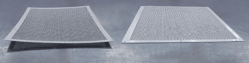

There are several ways to reduce the risk of oil canning in custom sheet metal fabrication:
- Review whether a tight flatness tolerance is functionally necessary
- Reduce large unsupported flat areas when the design allows it
- Design weldments with fewer pieces or shorter weld lengths when practical
- Consider tack, stitch, or spot welding instead of continuous seams when the application permits
- Use appropriate fixturing and weld sequencing during assembly
Preventing all distortion is not always possible, particularly on thin welded parts. If we identify an oil canning concern during DFM review, we’ll communicate it and work with you to identify a solution.
3. Flange Length
Flange length, sometimes called flange height, is the distance from a bend to the edge of the sheet metal or another feature.
If a flange is too short, there may not be enough material to properly span and engage the V-die during press brake forming.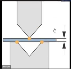
At Approved Sheet Metal, we use a simple flange formula as a DFM guideline for determining minimum acceptable flange length:
4x Material Thickness + Bend Radius = Minimum Acceptable Flange Length
For example, using 0.060" material and a 0.030" bend radius:
(4 × 0.060") + 0.030" = 0.270" minimum flange length
Tooling, material, thickness, bend angle, and surrounding geometry still need to be considered, but this formula provides a useful starting point when designing formed sheet metal parts.
4. Bend Radius
Bend radius is the inside radius created where sheet metal is formed. It is one of the most important dimensions to consider when designing a part for press brake forming.
Bend radius affects how the material forms and can influence bend calculations, flange geometry, cracking risk, and the tooling or process required to manufacture the part.
At Approved Sheet Metal, 0.030" is our preferred standard bend radius for many sheet metal parts up to 0.125" thick. Designing around a radius compatible with our standard forming processes can help avoid unnecessary tooling, setup, and lead time.
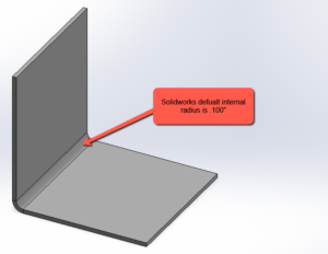
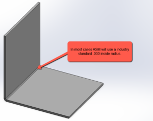
A few important things to remember about bend radius:
- The achievable bend radius depends on the material, thickness, tooling, and forming process
- Bend radius is one of the variables used when determining minimum flange length
- A CAD system’s default bend radius may not match the fabricator’s preferred manufacturing radius
- Specifying a bend radius equal to the material thickness is not a universal DFM rule
If your sheet metal is thicker than 0.125" or you’re uncertain about the best approach to your part’s bend radius, reach out to our team for guidance.
5. Gain
Sheet metal bend gain describes the dimensional change that must be accounted for when flat material is formed into a finished bent part.
When we form sheet metal, the material on the outside of the bend stretches while the material on the inside compresses. Accounting for that behavior is necessary to determine the correct flat size before the part is cut and formed.
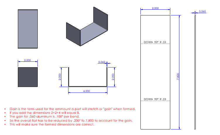
To calculate a part’s sheet metal bend gain, ASM uses an in-house formula that accounts for factors including material type, material thickness, and bend radius. These calculations inform our flat pattern and press brake programming so the formed dimensions match the drawing.
That means you generally do not need to manually compensate the flat pattern for our manufacturing process. Provide the formed 3D model and drawing requirements, and we can calculate the appropriate flat geometry for fabrication.
6. Bend Relief
A bend relief is a cut or clearance placed near the end of a bend to help prevent tearing, distortion, or interference during forming.
Bend relief becomes particularly important when a bend terminates near an adjacent flange, edge, or other geometry. Without enough relief, the material surrounding the bend may stretch, tear, or deform as the flange is formed.

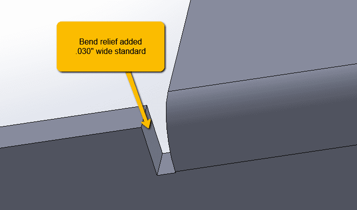
The exact relief geometry depends on the material thickness, bend radius, and surrounding part geometry. When relief is required and the design does not provide enough clearance, we can review the feature and recommend an appropriate solution.
For many applications, Approved Sheet Metal uses a standard 0.030" bend relief when appropriate. We’ll communicate with you before making a design change that affects the finished geometry. You can also learn how to add your own bend reliefs in SOLIDWORKS!
7. Tolerance Stackup
Tolerance stackup is the accumulated dimensional variation created when multiple toleranced features, bends, or components contribute to a final dimension.
Within a single sheet metal part, a dimension between two features cut on the same flat surface can generally be controlled more tightly than a dimension that crosses several bends. Each forming operation introduces another potential source of dimensional variation.
Within an assembly, the tolerances of individual components can also combine based on how the parts locate and mate with one another.
This is why a critical dimension that crosses three or four bends should not automatically be assigned the same tolerance as two laser-cut holes on the same surface.
When several features need to align, designers should identify the dimensions that actually control fit and function rather than applying unnecessarily tight tolerances throughout the entire part.
The best way to avoid tolerancing problems is to design around ASM’s standard sheet metal tolerances when possible. If a critical assembly dimension requires tighter control, our team can review the complete tolerance stack and recommend an appropriate manufacturing approach.
8. Forming Tabs
Forming tabs are temporary features added to a sheet metal part to provide a way to locate, hold, or form geometry that would otherwise be difficult to produce.
When a part is designed with unusual angles or geometry that interferes with the normal bending process, we can add forming tabs to the 3D model in SOLIDWORKS.
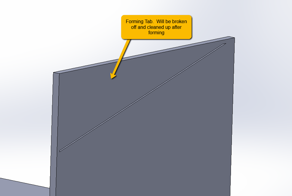
Why have you never seen forming tabs on your finished parts? Because they're temporary. After forming, we remove the tabs and deburr the affected area before the part ships.
Adding and removing forming tabs introduces some additional manufacturing time, but they can be an efficient solution for prototypes and low-volume parts that don't justify dedicated fixtures or tooling.
For higher-volume production, a dedicated fixture or another repeatable manufacturing method may make more economic sense.
9. Kerf
Kerf is the width of material removed by a cutting process. In sheet metal laser cutting, the laser beam removes a narrow path of material as it travels along the programmed cut.
If your sheet metal part includes an extra-long bend, you may also hear us refer to kerf cuts. These are intentionally added cuts that can reduce the amount of material being formed at once and therefore reduce the tonnage required for certain difficult bends.
“Kerf” is a fabrication term for the ma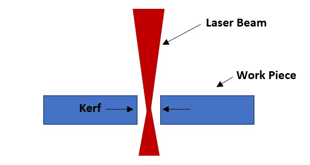 terial removed during laser cutting.
The actual kerf width varies depending on the material, thickness, laser, cutting parameters, assist gas, and other process variables. Laser programming compensates for the kerf so that the finished cut geometry meets the required dimensions.
When kerf cuts are intentionally added to assist with forming, those cuts can be welded and finished after the bending operation when the design requires it.
10. Crashing
Crashing describes a collision or interference that prevents a sheet metal part from being formed or unfolded as intended.
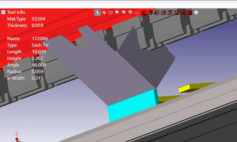
In CAD, crashing can occur when we attempt to flatten a 3D model and the part’s features collide or overlap, preventing the model from unfolding correctly.
On the shop floor, the term can also describe a physical interference between the part and the press brake tooling or machine during the bending sequence. Deep flanges, return bends, unusual angles, and complex formed geometry can all create situations where the part cannot clear the tooling during forming.
In some cases, we can prevent crashing by utilizing special tools, changing the bend sequence, or reorienting the part. Other situations require a design modification.
If a design revision is necessary, we’ll connect with you to discuss the options before proceeding.
11. Springback
Springback is the tendency of sheet metal to partially return toward its original shape after the forming force is removed.
When a press brake bends sheet metal, the material is intentionally deformed beyond its elastic range. Once the punch releases the material, some elastic recovery still occurs, causing the final bend angle to open slightly.
The amount of springback depends on several factors, including:
- Material type: Different alloys respond differently to forming.
- Material thickness: Thickness affects the relationship between the material and forming tooling.
- Bend radius: The radius influences how the material stretches and compresses during forming.
- Bend angle: Different formed angles may require different compensation.
- Tooling and forming method: Air bending, bottom bending, and other processes control the material differently.
Springback is one reason sheet metal forming is not simply a matter of programming the press brake to the exact finished angle shown on the drawing. The forming process may intentionally compensate for expected springback so that, after the material relaxes, the finished bend reaches the required angle.
Material consistency matters as well. Even when parts are produced from the same nominal material specification and thickness, normal material variation can affect forming behavior.
For engineers, the important takeaway is that material, thickness, bend radius, tooling, and required angle all work together. If a bend angle is particularly critical to fit or function, identify that requirement clearly on the drawing so it can be considered during DFM review and forming.
Bridging the Gap Between Part Design and Sheet Metal Services with Sheet Metal Fab Terms
Understanding the terminology your fabricator uses makes it easier to communicate design intent, recognize potential DFM issues, and make informed decisions when a part requires an adjustment.
Terms like bend radius, flange length, springback, tolerance stackup, and kerf aren't just shop-floor vocabulary. Each one describes a manufacturing consideration that can directly affect the cost, lead time, fit, and manufacturability of a custom sheet metal part.
At ASM, we’re committed to innovation, we believe in our team, and we value our customers. Helping design engineers and product developers bring their ideas to life is the heart of everything we do.
Ready to work with us? Request a quote!


