
Last updated on August 27th, 2026 at 10:53 am
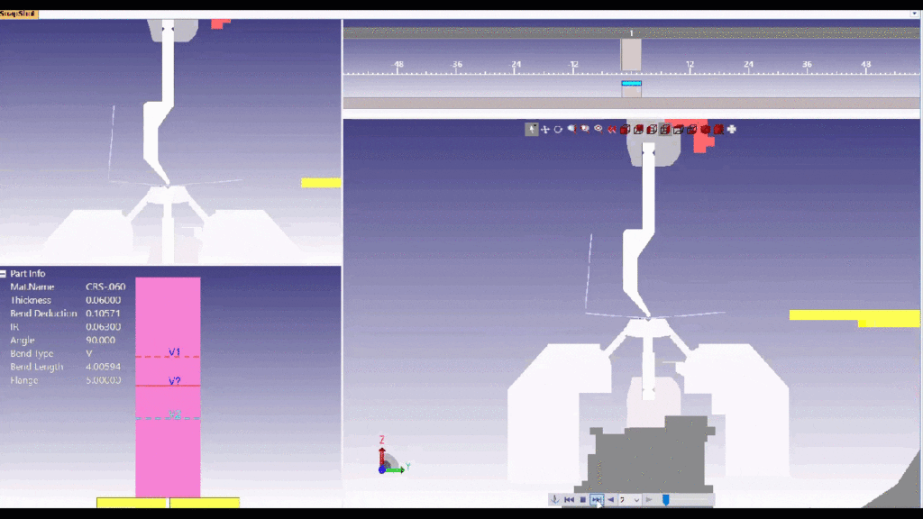
Deep U-shaped parts, boxes, channels, and return flanges can create press brake interference even when the geometry looks perfectly reasonable in CAD. Once one flange is formed, that material still has to physically clear the punch, die, ram, and previously formed features while the remaining bends are completed.
This means a part can flatten correctly in CAD and still be difficult or impossible to form using a conventional bend sequence.
Common factors that affect whether a complex sheet metal part can be formed include:
- U-channel depth
- Inside width
- Flange height
- Return flanges
- Part length
- Bend sequence
- Punch and die profile
- Material thickness
- Bend radius
If these conditions are not evaluated before production, the problem may not become obvious until the fabricator on the shop floor attempts the bend, creating unnecessary scrap, rework, and lost time.
Why a Part Can Flatten Correctly but Still Be Impossible to Bend
A valid flat pattern proves that the geometry can mathematically unfold. It does not prove that a real press brake punch, die, and machine can physically access every bend in the required sequence.
For example, a deep U-shaped part may flatten without any problem in SOLIDWORKS, but after the first side wall is formed, that flange may collide with a straight punch when the operator attempts the second bend.
This is why press brake tooling access and bend sequence should be part of the DFM review for deep or complex formed parts.
Solution 1: Change the Bend Sequence
Sometimes the simplest solution is to form the bends in a different order.
The sequence in which bends are made determines where previously formed material will be positioned during each later operation. Changing the sequence can sometimes provide the clearance needed to finish the part without changing the actual design.
This option is usually the first thing worth evaluating because it does not require additional tooling or modifications to the finished geometry.
Solution 2: Back Bending
When a conventional bend sequence still does not provide enough clearance, one technique ASM may evaluate is back bending.
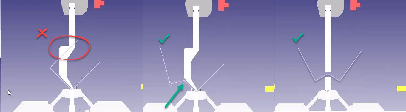
Back bending temporarily moves material out of the way so a later bend can clear the press brake tooling.
For a deep U-shaped part, we may first create an additional bend in the center of the blank so the part temporarily resembles a W. That temporary bend gives the already-formed material additional clearance while the critical bends are completed.
Once the difficult bends are finished, the temporary center bend is flattened back out.
Back bending can eliminate the need to split a part into multiple pieces and weld it back together, but it is not appropriate for every design.
The technique works best when:
- There is enough open material available for the temporary bend
- No other feature interferes with the area that needs to be flattened later
- The material and thickness can tolerate the additional forming operations
- The finished surface requirements allow the process
Back bending also adds forming operations and requires an experienced press brake operator who understands how the temporary bend will affect the rest of the part.
Solution 3: Use Different Press Brake Tooling
When the part geometry cannot clear standard straight tooling, the next option is often to select a different punch or die profile that provides more clearance.
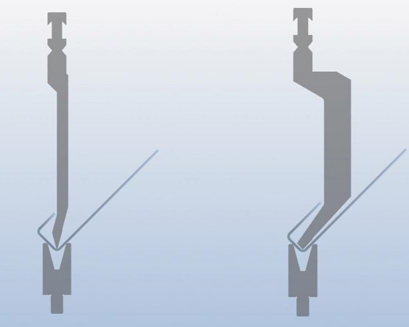
A common example is a gooseneck punch, sometimes called a swan-neck punch. Unlike a straight punch, a gooseneck punch has a relieved profile that creates space behind the tool for an already-formed flange.
This additional clearance can allow deep boxes, channels, return flanges, and other difficult geometry to be formed without the part crashing into the punch.
At Approved Sheet Metal, we use forming software and our knowledge of available tooling to evaluate the bend sequence and determine which punch and die combination gives the part the best chance of being formed successfully.
ASM maintains a broad library of standard press brake tooling, and in many cases we can solve the forming problem without ordering custom tooling.
Important tooling variables include:
- Punch profile: Straight, gooseneck, or another relieved geometry
- Punch height: Taller tooling can provide additional part clearance
- Die opening: The V-opening affects bend radius, tonnage, and flange requirements
- Tool segmentation: Segmented tooling may provide clearance around surrounding part geometry
- Material and thickness: Tool selection must also support the required forming force and bend radius
What Happens When Standard Press Brake Tooling Still Can’t Form the Part?
When a complex part cannot be produced with the original bend sequence and standard tooling, there are still several possible paths forward.
| Forming Problem | Possible Solution |
|---|---|
| Previously formed flange hits a straight punch | Use a gooseneck or other relieved punch |
| Deep U-shape cannot clear the tooling | Try a different bend sequence or back bending |
| Return flange traps the part | Change the forming sequence or revise the geometry |
| Required tooling profile is unavailable | Evaluate specialty or custom tooling |
| Geometry remains physically inaccessible | Split the design into multiple components and weld or fasten them together |
| Multiple bends create difficult finished dimensions | Review the tolerance strategy and identify the dimensions that are truly critical |
When a Design Change May Be Better Than Special Tooling
Sometimes the most cost-effective solution is a small design modification rather than a complicated forming process or custom tool.
Depending on the function of the part, possible changes include:
- Reducing the depth of a U-shaped channel
- Increasing the space between opposing walls
- Removing or relocating a return flange
- Changing a flange height
- Adjusting the bend radius
- Moving a feature away from a difficult bend
- Splitting one section into a separate component
If the design cannot be changed and the geometry still cannot be reached with available tooling, the part may need to be fabricated from multiple pieces and permanently joined using welding or another assembly method.
Forming Tolerance Stack-Up
Complex forming is not only about whether the press brake can physically make every bend. Engineers also need to consider how dimensional variation accumulates as bends are added.
Each formed feature introduces some process variation. When several bends reference one another, that variation can influence the final location of the last flange or feature.
Common areas affected by forming tolerance stack-up include:
- Bend-to-edge dimensions: Final flange length depends on the forming process and material response.
- Bend-to-bend dimensions: Variation can accumulate between multiple formed features.
- Finished opening width: Opposing walls may accumulate variation from both bends.
- Parallelism: Multiple bends can affect how parallel opposing walls or flanges remain.
- Material springback: Materials such as stainless steel and some higher-strength alloys can require additional compensation during forming.
The goal should be to identify the dimensions that are truly critical to the part’s form, fit, and function instead of applying unnecessarily tight tolerances to every formed feature.
DFM Strategies for Complex Sheet Metal Forming
Applying practical design for manufacturability principles can make deep and complex formed parts easier to produce without unnecessary tooling, secondary operations, or design revisions.
1. Use Realistic Tolerances
- Apply tight tolerances only where they directly affect fit or function.
- Remember that multiple bends can create cumulative dimensional variation.
- If a feature truly requires machining-level control after forming, discuss whether a secondary operation is appropriate.
2. Use Practical Bend Radii
- Use bend radii that are compatible with the material, thickness, and available press brake tooling.
- Avoid unnecessarily tight bend radii that increase the risk of cracking or require specialty tooling.
- Give the fabricator flexibility on inside radius when the exact radius is not functionally critical.
3. Keep Features Away from Difficult Bends
- Holes, slots, hardware, embossments, and other features positioned too close to a bend can distort during forming or interfere with tooling.
- Feature placement can also prevent back bending or alternate bend sequences if the temporary forming operation would affect the feature.
4. Avoid Unnecessary Return Flanges
- Return flanges can dramatically reduce tooling clearance because they create additional geometry that must pass around the punch and die.
- If a return flange is not functionally necessary, removing or modifying it can turn a difficult forming job into a standard press brake operation.
5. Provide a Complete 3D Model
- A formed 3D model allows the fabricator to review the actual finished geometry and evaluate possible bend sequences.
- Clearly identify the finished dimensions that are critical instead of relying only on the flat pattern.
6. Ask for DFM Review Before Freezing the Design
A design change that takes a few minutes in CAD can sometimes eliminate custom tooling, back bending, welding, or an otherwise difficult forming sequence.
Getting the fabricator involved before the geometry is locked gives the team more flexibility to find the fastest and most cost-effective manufacturing approach.
How ASM Approaches Difficult Formed Parts
When a deep box, U-shaped channel, return flange, or other complex geometry reaches our shop, we do not assume there is only one way to form it.
Our team evaluates the complete part, including tooling access, bend sequence, material, thickness, bend radius, tolerance requirements, and available press brake tooling.
The solution may be as simple as changing the bend sequence. For more difficult geometry, we may use back bending, gooseneck tooling, another press brake setup, a small design modification, specialty tooling, or a multi-piece fabricated solution.
That DFM review can prevent the frustrating situation where a part looks correct in CAD but cannot physically make it through the press brake.
Ready to have ASM review your next difficult formed part? Design your part with manufacturability in mind, then request a quote and send us your 3D model and drawing.
Sheet Metal Design for Manufacturing
FREE eBOOK DOWNLOAD
Design parts with the sheet metal fabrication process in mind. Reduce cost and get parts on your desk faster! Learn about the following best practices when designing sheet metal parts:
- Hems & Offsets
- Notches & Tabs
- Corners & Welding
- Uniform Thickness and more!



