Last updated on January 20th, 2025 at 10:11 am
We’re thrilled to share that we created a proprietary tool to help sheet metal fabrication customers design louvers in SOLIDWORKS. 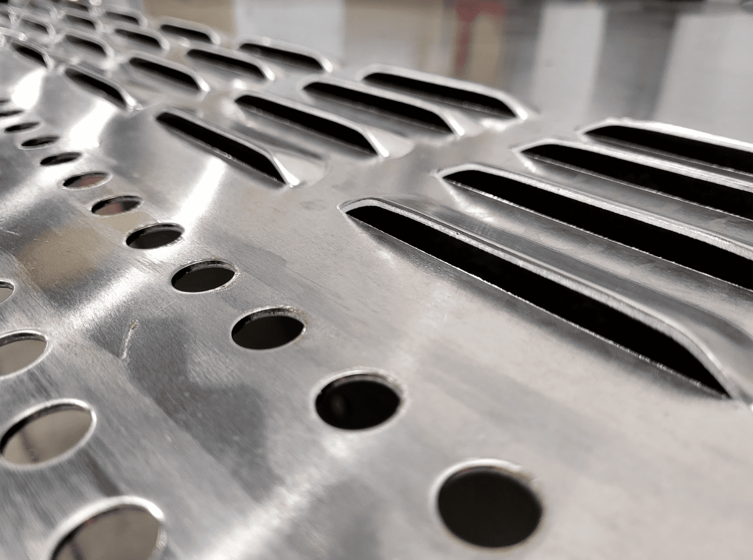
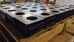
We love louvers. These press-formed features are commonly found in applications that require airflow and light penetration, such as microwaves and ventilation systems.
The most common louvers consist of a single-stroke form created with a turret punch press or press brake. Using standard tooling for louvers is one great way to save time and money on a custom sheet metal fabrication.
You may be thinking: “Louvers seem like simple enough features, so why do I need a unique design tool in SOLIDWORKS to ensure manufacturability? Doesn't SOLIDWORKS already have a tool for designing louvers?”
Table of Contents
- 1 The Problem with Designing Louvers in SOLIDWORKS
- 2 Introducing: Approved Sheet Metal's Proprietary Louver Tool
- 3 ASM Provides Two Standard Louver Sizes in SOLIDWORKS
- 4 Download Approved Sheet Metal's SOLIDWORKS Tool for Louvers
- 5 Sheet Metal CAD Tooling Library
- 6 Sheet Metal Louver Design FAQ
- 6.0.1 What are louvers and where are they commonly used?
- 6.0.2 Why do I need a unique design tool in SOLIDWORKS for designing louvers? Doesn't SOLIDWORKS already have a louver design tool?
- 6.0.3 What are the benefits of using Approved Sheet Metal's proprietary Louver Tool?
- 6.0.4 What are the standard sizes of louvers available through Approved Sheet Metal's Louver Tool?
- 6.0.5 What should I consider when designing custom sheet metal fabrications with louvers?
Applications of Louvers in Sheet Metal Fabrication
Louvers are versatile features found in a wide range of industries and applications. Their primary functions—facilitating airflow, providing ventilation, and allowing light penetration—make them indispensable in many designs. Here are some key applications:
- HVAC Systems
Louvers are essential in heating, ventilation, and air conditioning systems, ensuring proper airflow and temperature regulation in commercial and residential spaces. - Electronics Enclosures
In electronics and server cabinets, louvers help maintain optimal temperatures by allowing heat to escape while protecting components from dust and debris. - Automotive Components
Vehicles often use louvers in air intakes and exhaust vents to improve engine cooling and aerodynamics while maintaining structural integrity. - Appliances
Louvers are a common feature in household and industrial appliances, such as microwave ovens, refrigerators, and dryers, where ventilation is critical for performance and safety. - Architectural Design
In building exteriors and interiors, louvers contribute to both functionality and aesthetics, aiding in natural ventilation and reducing energy consumption. - Industrial Equipment
Industrial machines and equipment use louvers to safeguard motors and systems by regulating airflow and preventing overheating.
The Problem with Designing Louvers in SOLIDWORKS
Yes, SOLIDWORKS sheet metal has a louver tool to help streamline the design process. The only problem? The standard, "out-of-the-box" louver SOLIDWORKS provides is not manufacturable!
It has angles and slopes that simply aren't achievable in the real world. If we were to try manufacturing louvers to SOLIDWORKS’ default specifications, we’d end up ripping the material and ruining the part.
Challenges Without the Proprietary Tool
Designing louvers in SOLIDWORKS without a proprietary tool like Approved Sheet Metal’s can present several significant challenges:
- Non-Manufacturable Designs
The default SOLIDWORKS louver tool generates features with angles, slopes, and dimensions that are often not achievable in real-world manufacturing. Attempting to fabricate these designs can lead to material tearing, part failure, and wasted production resources. - Time-Consuming Adjustments
Engineers often need to manually modify default louver designs to meet manufacturing requirements. This process can involve extensive trial and error, delaying projects and increasing labor costs. - Incompatibility with Standard Tooling
Standard SOLIDWORKS louvers may not align with the dimensions and capabilities of commonly used tooling, forcing manufacturers to invest in custom tooling or rework designs. - Lack of Design Flexibility
Without a custom tool, designers face limitations in adjusting key parameters such as size, spacing, and material thickness, which can hinder innovation and customization. - Increased Risk of Errors
Manual adjustments and workarounds can lead to errors in design files, which may only be discovered during manufacturing, resulting in costly rework or scrapped parts.
Introducing: Approved Sheet Metal's Proprietary Louver Tool
Luckily, all hope for an easy method of designing manufacturable louvers is not lost!
The SOLIDWORKS experts at Approved Sheet Metal have created our own louver tool that boasts these big benefits:
- Compatible with SOLIDWORKS
- Simplifies louver design without jeopardizing manufacturability
- Works with our standard in-house tooling
And? Our louvers look very similar to the default louvers in SOLIDWORKS.
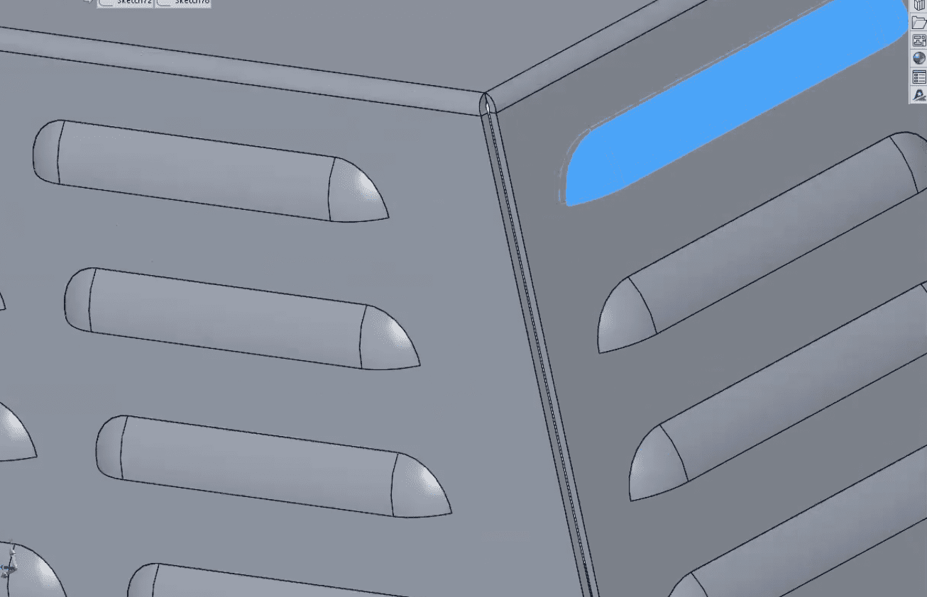
ASM Provides Two Standard Louver Sizes in SOLIDWORKS
Through our proprietary SOLIDWORKS louver tool, you can make louvers with these measurements:
- Louver #1
- Length: 2.985"
- Width: 0.615"
- Height: 0.210" (measured from the top of the sheet to the top of the form)
- Suitable for material thickness ranges between 0.047" and 0.080"
- Louver #2
- Length: 4.000"
- Width: 0.750"
- Height: 0.310" (measured from the top of the sheet to the top of the form)
- Suitable for material thickness ranges between 0.060" and 0.100"
It's important to note that the distance from the front edge to the formed edge is typically around 0.950", and the distance between the formed louvers themselves is 0.250". The larger the louver, the more these dimensions increase, so please keep that in mind when designing your custom sheet metal fabrication.
Additionally, if you're working with thicker materials than the ranges listed, please ask us about other solutions. We created this tool to streamline the louver design process, but we welcome custom projects that require more complex engineering.
Download Approved Sheet Metal's SOLIDWORKS Tool for Louvers
Are you ready to start using our louver tool for your next custom sheet metal fabrication?
We've made it really easy to add our standard louvers to your SOLIDWORKS platform. Simply download the files here, and upload them into SOLIDWORKS.
Louver #1

Louver #2

Watch this quick video to learn exactly how to download our standard louvers and where you can find our louver tooling in SOLIDWORKS.
Any questions? Feel free to contact us; we'd be happy to help!
Sheet Metal CAD Tooling Library
EMBOSSMENTS & LOUVERS
Say goodbye to the tedious process of designing basic sheet metal features from scratch. Our 3D tooling library empowers mechanical engineers and product developers to accelerate their design process by providing pre-designed tooling options. Focus on the creative aspect of your projects and deliver exceptional results faster.