Last updated on August 17th, 2026 at 08:48 am
Do you need support designing countersinks into your custom fabrication?
Countersinks are conical holes that allow flat-head screws, rivets, and other hardware to sit flush or below the surface of a sheet metal part. The challenge is that a countersink must match the selected fastener while also fitting within the available material thickness.
Here’s what engineers need to know about designing countersinks, including Approved Sheet Metal’s proprietary formula for calculating the pre-punch hole used in our formed countersink process.
Important Countersink Measurements
There are three primary dimensions to understand when designing a countersink:
| Dimension | What It Means | Why It Matters |
|---|---|---|
| Major Diameter | The larger diameter at the top of the countersink | Controls how the fastener head seats in the material |
| Minor Diameter | The smaller through-hole at the bottom of the countersink | Provides clearance for the screw or rivet shank |
| Included Angle | The angle of the conical countersink | Must match the head angle of the selected fastener |
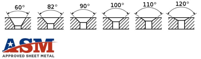
Common countersink angles include:
- 82° for many inch-series flat-head screws commonly used in American manufacturing
- 90° for many metric countersunk fasteners
- 100° for certain aerospace fasteners
- 120° for certain rivet and countersink applications
The important rule is to match the countersink angle to the actual fastener being used. Do not select the countersink angle based only on the industry or application.
Select the Fastener Before Designing the Countersink
The fastener should be selected before the countersink geometry is finalized because the hardware determines several important dimensions.
Review:
- Fastener head diameter
- Fastener head angle
- Screw or rivet shank diameter
- Required clearance hole
- Required flushness
- Material thickness
- Clearance to any mating component below the sheet
If the screw head is larger or deeper than the material can accommodate, the countersink cannot simply be made deeper without eventually breaking through the sheet.
Can Sheet Metal Be Too Thin for a Countersink?
Yes. A countersink requires enough material thickness to create the required major diameter and included angle while still leaving usable material around the minor opening.
As the countersink gets wider or deeper, more of the sheet thickness is consumed by the conical feature. If the material is too thin, the countersink may break completely through the sheet, leave an impractically sharp edge, or create a weak or distorted feature.
This is one reason countersink geometry should be reviewed together with material thickness rather than treated as an independent hole feature.
When very thin material must accept a flat-head fastener, alternatives may include a different fastener style, undercut hardware, formed geometry, or another fastening method depending on the application.
Different Types of Countersinks
There are two primary ways we create countersinks in custom sheet metal parts: machining the feature or forming it with punch tooling.
1. Machined Countersinks
Machined or "cut" countersinks remove material to create the conical seat.
The through-hole can first be produced by laser cutting, punching, drilling, or another cutting operation. A countersink tool is then aligned with the hole and removes material until the required major diameter and depth are achieved.
Machined countersinks are well suited to prototypes, low-volume production, special geometries, or situations where dedicated forming tooling is not available.
Advantages include:
- No dedicated form tool may be required
- Flexible major diameter and depth
- Useful for prototype and low-volume quantities
- Good option when the material is not a strong candidate for forming
The tradeoff is that each countersink requires a secondary machining operation, so cycle time can become significant as the number of features and parts increases.
2. Formed Countersinks
A formed countersink creates the conical feature by displacing material rather than simply cutting it away.
At Approved Sheet Metal, formed countersinks can be produced using CNC punch or turret tooling when the material, thickness, and required geometry are compatible with the available tool.
First, a pre-punch hole is created. A punch and die shaped for the required countersink geometry then apply pressure to the sheet. During this coining operation, material flows around the hole to create the countersunk seat.
Because material moves during forming, the pre-punch hole is not necessarily the same size as the desired finished minor diameter. That relationship is exactly what our proprietary countersink formula is designed to calculate.
Formed countersinks can be particularly efficient when:
- The geometry matches available punch tooling
- The material has suitable formability
- A part contains multiple countersinks
- The same feature will be repeated across production quantities
Machined vs. Formed Countersinks
| Factor | Machined Countersink | Formed Countersink |
|---|---|---|
| How It Is Created | Material is removed | Material is displaced and formed |
| Dedicated Form Tool | Usually not required | Required |
| Prototype Flexibility | Excellent | Depends on available tooling |
| Feature Flexibility | High | More dependent on tool geometry |
| Production Efficiency | Each feature requires machining time | Very efficient when established in the punch process |
| Material Formability | Less critical | Important |
| Best Fit | Low volume or special geometry | Repeat geometry compatible with available tooling |
How Material Affects Countersink Manufacturability
Material type and thickness influence whether a countersink is better machined or formed.
Ductility
Formed countersinks require the sheet material to plastically move into the required shape without excessive cracking or tearing. More formable materials are generally better candidates for aggressive formed features.
For example, 5052 aluminum is typically more suitable for forming than 6061-T6 aluminum, which generally requires more conservative formed geometry.
Material Thickness
The material must be thick enough to support the required countersink depth and major diameter. A countersink that works well in one sheet thickness may become impossible if the same design is changed to a thinner gauge.
Material Hardness
Harder materials can require more forming force and may be less suitable for deep formed countersinks. Hardness also affects machining tool wear and process selection.
Coated Materials
When a countersink is formed in pre-coated material, the forming operation can affect the coating around the feature. If corrosion resistance or coating appearance is critical, that should be considered before selecting the manufacturing method.
The best process depends on the complete combination of material, thickness, countersink geometry, quantity, and available tooling rather than the material name alone.
How Close Can a Countersink Be to an Edge or Bend?
Countersinks need enough surrounding material to support the feature.
If the major diameter approaches an outside edge, nearby hole, bend, or another formed feature, the countersink can break through the surrounding material or cause distortion during forming.
The required clearance depends on the countersink diameter, material thickness, forming method, and nearby geometry. If a countersink must be positioned close to an edge or bend, it should be reviewed during DFM rather than relying on one universal spacing rule.
What Does “Flush” Mean for a Countersunk Fastener?
The purpose of a countersink is often to allow a fastener head to sit flush with the sheet metal surface, but the required condition should be clear when it affects function or appearance.
A countersunk fastener may be designed to sit:
- Flush with the surrounding surface
- Slightly below flush
- Slightly proud of the surface when the application allows it
If the screw head must meet a specific flushness requirement for clearance, sealing, sliding, cosmetics, or assembly, identify that requirement on the drawing.
Our Proprietary SOLIDWORKS Sheet Metal Formula for Correct Countersink Measurements
If you've read our blog before, you probably know that we are SOLIDWORKS® enthusiasts here at Approved Sheet Metal. But SOLIDWORKS® will not necessarily tell you whether every countersink you model is practical to manufacture.
For example, you can model a countersink whose required major diameter and angle consume more material thickness than the part actually has. You can also position a large countersink so close to an edge or vertical feature that the geometry becomes impractical to form.
Our team can review your design in SOLIDWORKS® and calculate the required geometry using the manufacturing process we use on our floor.
For formed countersinks, Approved Sheet Metal uses a proprietary formula to calculate the appropriate pre-punch hole while maintaining approximately a 0.005" flat around the bottom of the formed countersink.
Our Countersink Formula:
Pre-Punch Hole Size = B – [(B – C) × .75]
Where:
- B = Major diameter, the largest opening at the top of the countersink
- C = Desired finished minor diameter, the opening at the bottom of the countersink
Example of the ASM Countersink Formula
If the desired countersink has:
- Major diameter (B): 0.250"
- Finished minor diameter (C): 0.125"
The calculation is:
0.250 – [(0.250 – 0.125) × .75]
0.250 – (0.125 × .75)
0.250 – 0.09375 = 0.15625"
The calculated pre-punch hole would therefore be approximately 0.156".
This larger starting hole accounts for the way material moves during the coining operation while preserving the flat needed around the finished minor opening.
The formula is an Approved Sheet Metal manufacturing guideline for our formed countersink process. The final manufacturability of the feature still depends on the material, thickness, countersink angle, tool geometry, and surrounding part design.
Why the Major and Minor Diameters Matter
The countersink must create enough room for the fastener head without removing or displacing so much material that the bottom of the feature becomes unstable.
If the geometry is pushed too far, the material around the minor diameter can become too thin or produce a burr or sharp edge. That can prevent mating components from sitting flat or interfere with the fastener installation.
This is why countersink design should consider major diameter, minor diameter, angle, material thickness, and fastener geometry together rather than treating each dimension independently.
Countersinks are common in sheet metal fabrication, but the right geometry depends heavily on the hardware and the material receiving it. If you would like a precision sheet metal expert to review your countersink design, please get in touch with us!
And if you're ready to start your next sheet metal fabrication project, we'd love to show you what we can do. Request a quote to get started today.
Sheet Metal Design for Manufacturing
FREE eBOOK DOWNLOAD
Design parts with the sheet metal fabrication process in mind. Reduce cost and get parts on your desk faster! Learn about the following best practices when designing sheet metal parts:
- Hems & Offsets
- Notches & Tabs
- Corners & Welding
- Uniform Thickness and more!