Last updated on February 4th, 2026 at 01:10 pm
When it comes to successful sheet metal fabrication, part design is just as important as manufacturing—and Approved Sheet Metal uses only the best technology for both.
Table of Contents
- 1 Essential SOLIDWORKS Design Tips
- 2 *BONUS* Flat Pattern Optimization in SOLIDWORKS
- 3 Sheet Metal Design for Manufacturing
- 4 SOLIDWORKS Sheet Metal Design FAQ
- 4.0.1 What makes part design crucial in successful sheet metal fabrication at Approved Sheet Metal?
- 4.0.2 How does SOLIDWORKS help in designing complex sheet metal parts at Approved Sheet Metal?
- 4.0.3 How does Approved Sheet Metal streamline the process of adding hardware to sheet metal designs?
- 4.0.4 What are some essential SOLIDWORKS design tips recommended by ASM for sheet metal fabrication?
- 4.0.5 What design tips can you offer for successful sheet metal fabrication using SOLIDWORKS at Approved Sheet Metal?
Essential SOLIDWORKS Design Tips
Here are three of Steve’s can’t-miss SOLIDWORKS design tips:
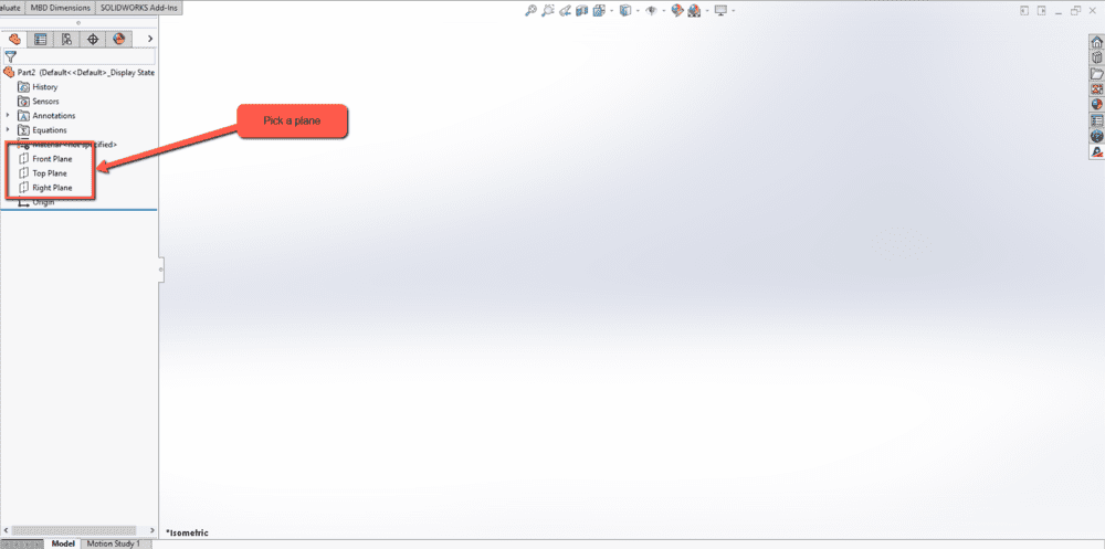
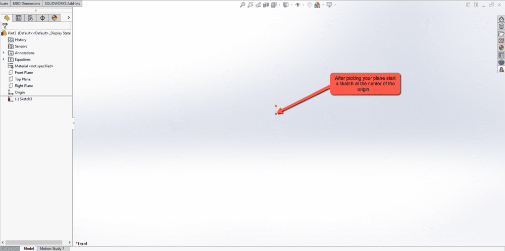
- Start by centering your SolidWorks sheet metal design
While there are a few different ways you can begin designing a custom sheet metal part, Steve recommends starting in the center of your design area.
Sometimes, designers will draw a feature skewed or off to the side without thinking it matters—but it does. Think of your design area as a canvas, and place the part's center right in the middle of it.
This approach offers more flexibility and freedom from the start of the design process. It can even prevent rework should you eventually decide to incorporate techniques such as mating and mirroring.
- For complex designs, use the shell tool
SOLIDWORKS has a sheet metal feature that allows engineers to draw their parts one bend at a time. This solution is fine for simple sheet metal parts, but it can make designing complex parts challenging.
Instead, draw your basic shape using the shell tool to maintain uniform material thickness. Once your shell is rendered, you can convert the design to sheet metal fabrication.
If you want an even easier solution, send your shell to our team here at Approved Sheet Metal, and we'll convert it for you.
- Streamline hardware additions
Without knowing it, most engineers are doing too much work to add hardware to their designs. They'll download hardware as a 3D CAD file from a supplier website such as PennEngineering®, then spend 4-5 clicks putting it in their model.
You might think 4-5 clicks isn't time-consuming, but if you’re working on dozens of pieces of hardware at once, all those clicks add up to valuable time wasted.
At Approved Sheet Metal, we leverage an efficient approach with SOLIDWORKS that involves dragging and dropping hardware so that it auto-snaps into the appropriate holes.
*BONUS* Flat Pattern Optimization in SOLIDWORKS
When designing a custom sheet metal part, the flat pattern is what ultimately gets cut, punched, or laser-processed on the shop floor. That’s why optimizing the flat pattern early in your design process can reduce rework, improve part accuracy, and speed up production.
1. Use the Sheet Metal Tools from the Start
Avoid modeling a solid part and then trying to convert it to sheet metal as an afterthought. SOLIDWORKS has a dedicated Sheet Metal feature set that handles bends, reliefs, and flat pattern generation automatically. These tools ensure accurate bend allowances and a clean flat layout from the beginning.
2. Respect Minimum Bend Radii
Each material has a minimum bend radius based on its thickness and ductility. Using a bend radius that’s too tight may cause cracking or springback, resulting in part failure or poor fit. Always apply bend tables or custom K-factors tailored to your shop’s equipment and materials.
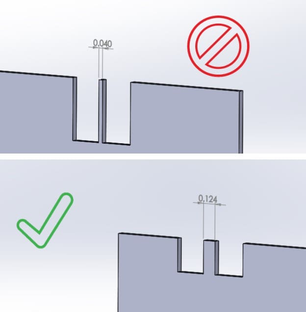
3. Avoid Overlapping or Interfering Geometry
Watch out for overlapping flanges, small tabs, or cutouts that interfere with bend zones. These can create issues when the part is unfolded, especially if the geometry becomes distorted or unmanufacturable.
Tip: Use “Bend Region” visualization in SOLIDWORKS to quickly identify and correct potential problem areas before releasing a flat pattern for cutting.
4. Simplify Bend Reliefs
For internal corners or adjacent flanges, add tear-drop or obround reliefs to avoid stress fractures during forming. SOLIDWORKS can automatically apply bend reliefs based on your sheet metal settings.
5. Flatten from the Right Configuration
In multi-configuration models, always verify that you’re creating the flat pattern from the correct part configuration. This ensures that what gets cut on the laser or turret exactly matches the intended formed part.
6. Export for Manufacturing
When you're ready to release the part, export the flat pattern as a DXF or DWG with bend lines and layer separation (cut vs. etch). Most CAM systems require specific layer naming, which you can customize directly in the “Export to DXF/DWG” dialog box.
If you're struggling with the custom metal fabrication design process or currently working with a manufacturer that isn't taking the time to support you, we would love to help.
Request a quote today, and let's get your design ready for the shop floor!
Sheet Metal Design for Manufacturing
FREE eBOOK DOWNLOAD
Design parts with the sheet metal fabrication process in mind. Reduce cost and get parts on your desk faster! Learn about the following best practices when designing sheet metal parts:
- Hems & Offsets
- Notches & Tabs
- Corners & Welding
- Uniform Thickness and more!
")