
Last updated on August 17th, 2026 at 08:14 am
Choose the Right Gauge at Approved Sheet Metal
When you’re working with sheet metal, choosing the right gauge or thickness may seem simple. But material thickness affects much more than the strength of the finished part. It can influence bend radius, minimum flange length, hardware selection, formed features, weight, cost, and lead time.
Just as importantly, not every nominal material thickness is readily available in every material. Designing around a thickness your fabricator can source quickly can make a significant difference in how quickly and economically your parts can be produced.
Material Thicknesses: What’s Really Out There?
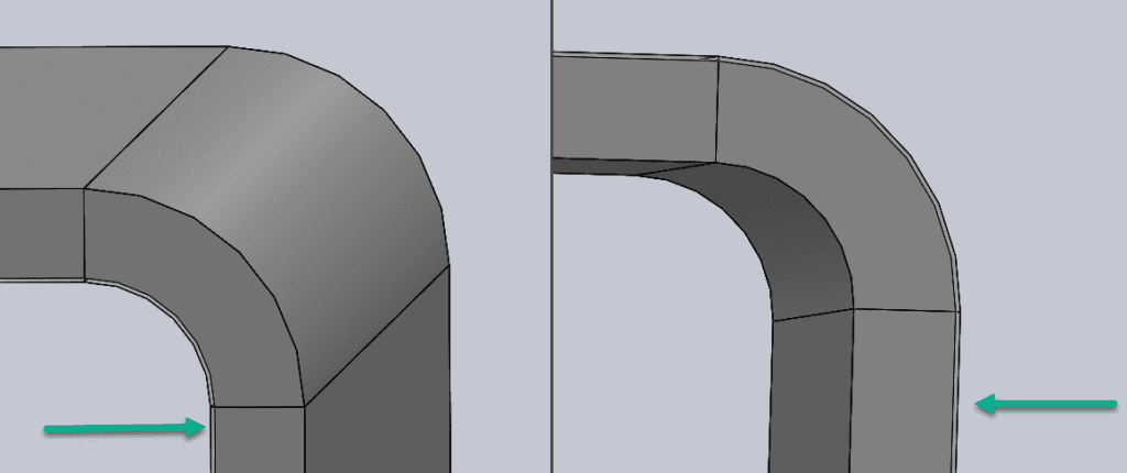
Not all sheet metal fabrication shops have the same materials and thicknesses readily available. A thickness that looks standard in a design table or CAD system may be uncommon in a particular alloy, difficult to source locally, or only available with a longer material lead time.
The last thing you want is to complete a design around a specific material thickness and discover during quoting that the material is difficult or expensive to source. Selecting the material after the design is complete can also create additional work because changing thickness can affect bends, mating surfaces, hardware, formed features, and assembly dimensions.
So, what’s the best way to avoid these problems? Ask your manufacturer which sheet metal materials and thicknesses are readily available through their normal supply chain, then consider those options as you design the part.
Sheet Metal Gauge vs. Thickness: What’s the Difference?
Sheet metal gauge is a numbering system used to identify material thickness, but a gauge number does not represent one universal thickness across all materials.
For example, the actual thickness represented by a particular gauge of steel is not necessarily the same as that gauge number in aluminum or another material. Gauge numbers can therefore create confusion when the material itself is not clearly identified.
For manufacturing, the actual material specification and thickness are what ultimately matter. A drawing that clearly identifies the material and nominal thickness gives the fabricator more useful information than a gauge number by itself.
This becomes especially important when changing materials. If a design moves from steel to aluminum, for example, you should not assume that keeping the same gauge number means keeping the same physical thickness or performance.
Design Implications of Material Thickness
The thickness of the sheet metal you select can affect the design, functionality, and manufacturability of your part. Choosing the appropriate thickness means balancing strength and weight with the forming, fastening, cutting, finishing, and sourcing requirements of the finished component.
1. Bend Radius and Formability
Material thickness is one factor that determines how a sheet metal part can be formed, but thickness should never be considered by itself.
The material and alloy matter too. For example, 5052 aluminum is generally a better choice for tighter formed features than 6061-T6, which typically requires larger bend radii to reduce the risk of cracking.
As material gets thicker, the tooling, forming force, minimum flange requirements, and practical bend radius can also change. A bend that works well in one thickness should therefore be reviewed before carrying the same geometry into a substantially thicker or thinner material.
2. Structural Integrity
Thicker sheet metal generally provides more stiffness and strength, but increasing thickness is not the only way to make a sheet metal part more rigid.
Thinner material can often be strengthened through part geometry, including:
- Flanges
- Ribs and formed features
- Gussets
- Hems
- Additional bends or returns
Using formed geometry to increase stiffness can sometimes provide the required performance without the added weight and material cost of moving to a thicker sheet.
On the other hand, material that is too thin for a large unsupported surface can be more susceptible to deflection, buckling, or visible oil canning.
3. Fastening and Joining
Material thickness affects the fastening and joining methods available for a sheet metal part.
Welding techniques, PEM-style inserted hardware, rivets, rivnuts, countersinks, and other fastening methods all have thickness-dependent design requirements.
For example, self-clinching hardware is selected partly according to the thickness and material into which it will be installed. A hardware callout that works in one sheet thickness may not be appropriate if the material is changed later.
The same consideration applies to countersinks. The material must provide enough thickness for the required countersink geometry without creating an impractical or weakened feature.
4. Tolerances and Mating Parts
Sheet metal has a nominal thickness, but actual material thickness can vary within the applicable material specification.
That variation matters when the sheet thickness itself contributes to a mating dimension or tolerance stack. Changing from one nominal thickness to another can also shift inside and outside surfaces after forming, which can affect fit within an assembly.
This is why even a relatively small material-thickness change should be reviewed when a part has tight mating surfaces, hardware locations, or other dimensions that depend on the material thickness.
If multiple fabricated components need to fit together, the complete assembly should be considered to ensure proper fit.
5. Laser Cutting, Punching, and Cut Features
Material thickness also affects how parts are cut.
As material becomes thicker, laser cutting generally requires more processing time and different cutting parameters. Material thickness can also influence piercing, edge condition, minimum practical feature geometry, and the punching tools or processes available for the part.
Rather than assuming thinner material always allows smaller features or thicker material requires larger ones, critical holes, slots, narrow sections, and other small features should be reviewed based on the specific material and cutting process.
6. Weight and Cost
Increasing material thickness increases the amount of material in every part. That affects both finished weight and material cost.
For a small bracket, the difference may be relatively minor. Across a large enclosure, assembly, or higher-volume production run, increasing thickness can add substantial material weight and cost.
The goal is to use enough material to meet the functional requirements of the part without adding thickness that provides little additional benefit.
7. Secondary Processes
Material thickness influences many of the secondary and forming operations used in custom sheet metal fabrication.
Examples include:
- Embossments
- Louvers
- Countersinks
- Dimpled or formed holes
- Hardware insertion
- Welding
- Press brake forming
Changing material thickness after these features have been designed can change whether they remain compatible with the available tooling and manufacturing process.
How Material Thickness Affects Sheet Metal DFM
Several common sheet metal DFM guidelines are directly related to material thickness. This is one reason material selection should happen early in the design process.
Minimum Flange Length
At Approved Sheet Metal, we use a practical starting guideline for minimum flange length:
Minimum Flange Length = (4 × Material Thickness) + Bend Radius
As material thickness increases, the minimum practical flange length increases as well. Changing material thickness without reviewing short flanges can therefore create forming problems.
Punch-Formed Features
Material thickness also affects punch-formed features such as louvers and embossments.
As a general Approved Sheet Metal DFM guideline, the height of a punch-formed feature should typically remain within approximately 3 times the material thickness when using standard tooling.
A 0.060" thick sheet, for example, would have a recommended formed feature height of approximately 0.180" under the 3:1 guideline.
Bend Radius
At Approved Sheet Metal, 0.030" is our preferred standard bend radius for many sheet metal parts up to 0.125" thick. The appropriate radius still depends on material type, alloy, thickness, tooling, and the specific forming operation.
This is particularly important when working with materials that are less forgiving during forming. A bend radius appropriate for 5052 aluminum should not automatically be assumed to work for 6061-T6 at the same thickness.
Hardware and Countersinks
Inserted hardware and countersinks are also tied directly to material thickness.
Self-clinching hardware has minimum sheet-thickness requirements, while countersinks require sufficient material to create the required geometry. If either feature is critical to the design, check its requirements before changing the material thickness.
Choosing the Right Sheet Metal Gauge at Approved Sheet Metal
Rapid delivery is one of our top priorities, so we keep common materials and gauges on hand and work with suppliers to source commonly used sheet metal quickly.
When lead time is important, designing around a material and thickness that is already available or readily sourced can eliminate unnecessary delays before fabrication even begins.
That doesn't mean you should simply select the closest available thickness. Any material change still needs to meet the strength, weight, forming, hardware, tolerance, and assembly requirements of the part.
Can Changing Sheet Metal Thickness Reduce Lead Time?
Yes. If a specified thickness is difficult to source but a nearby standard thickness is readily available, changing material thickness can sometimes reduce both sourcing lead time and material cost.
However, even a small thickness change can affect:
- Inside and outside formed dimensions
- Bend geometry
- Minimum flange lengths
- Mating surfaces
- Hardware compatibility
- Part weight and strength
- Tolerance stackups
The alternative thickness should therefore be reviewed before simply substituting material on the shop floor.
Case Study: No Standard Size, No Problem!
One of our customers recently asked us to assemble over 100 sheet metal components. They had designed the structural part of the assembly using .187" thick steel.
The problem wasn't whether we could fabricate the part. It was material availability. In our local supply chain around Hudson, New Hampshire, only one of our suppliers offered the specified thickness. Ordering from that source would have extended the material lead time to 3-4 days instead of just 1 and increased the material cost by 30% per pound.
So, how did we solve their problem?
We recommended .197", or 7 GA, steel instead. Although the nominal thickness difference was only .010", we still needed to make sure the change wouldn't create discrepancies in form, fit, or function.
The inside and outside surfaces of a formed sheet metal part shift when material thickness changes, so we reviewed the mating geometry and tolerance stack before making the substitution.
To give the team on our shop floor accurate geometry, we used SolidWorks to update the CAD models based on the actual material thickness being used.
The result was a readily available material that allowed us to maintain the short lead time while saving the customer 30% per pound on material.
The lesson isn't simply to choose a thicker or more common material. It's to consider material availability as part of DFM. A nearby standard thickness can sometimes provide the same required function at lower cost and with a shorter lead time, as long as the complete design is reviewed before making the change.
Are you unsure about the ideal material thickness for your part? Contact our team before finalizing the design. We can help you evaluate material availability, thickness, and manufacturability so you can choose the right option for your part.
Recommended Default Sheet Metal Tolerances
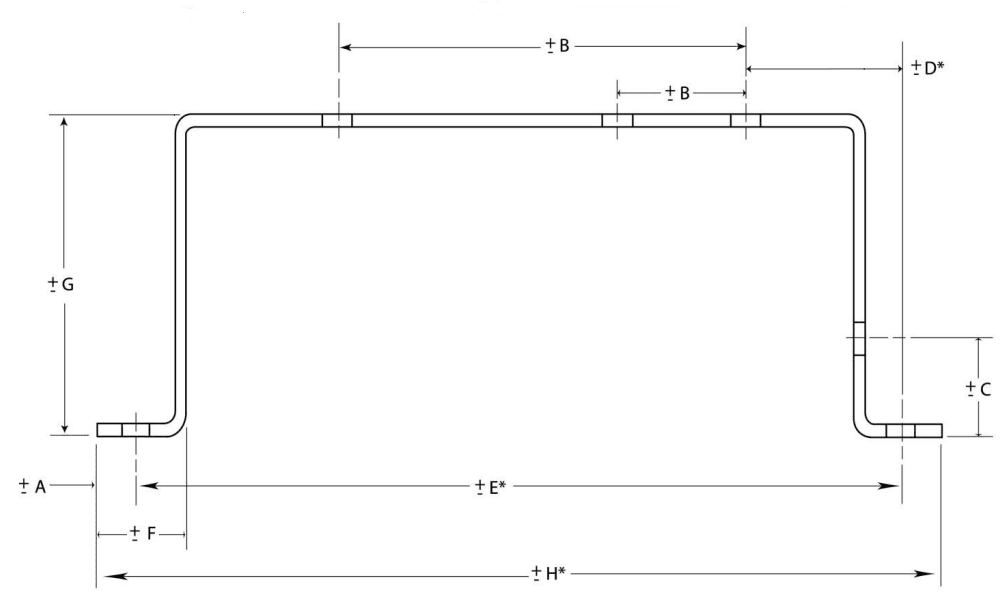
| DIM | Tolerance (MM) | Tolerance (Inches) | Description |
| A | ± 0.13 | ± 0.005 | Sheared Edge to Hole |
| B | ± 0.13 | ± 0.005 | 2 Holes on One Surface |
| C | ± 0.25 | ± 0.010 | Formed Edge to Hole |
| D* | ± 0.76 | ± 0.030 | Holes Across 2 Bends |
| E* | ± 0.76 | ± 0.030 | Holes Across 4 Bends |
| F | ± 0.25 | ± 0.010 | Sheared Edge to Bend |
| G | ± 0.38 | ± 0.015 | Across 2 Bends |
| H* | ± 0.76 | ± 0.030 | Formed Part |
Noted dimensions are to be taken while the part is in a restrained condition. Noted dimensions are for parts within a 12” envelope.
* Dimensions D, E and H are not recommended forms of dimensioning
These tolerances are recommended and best practices. We can obtain tighter tolerances (depending on part geometry/ construction), contact us for more information


