
Last updated on August 17th, 2026 at 08:21 am
Bump forming can be an excellent solution for prototype and low-volume sheet metal parts that require a large or cylindrical radius without dedicated radius tooling.
Is it better to bump form a part or use dedicated tooling? The answer depends on the required radius, material, part size, tolerance, production quantity, and how smooth and repeatable the finished profile needs to be.
For prototypes and lower-volume parts, bump forming can provide a flexible way to create large-radius bends while avoiding the cost and lead time associated with dedicated tooling.
What Is Bump Forming?
Bump forming, also called bump bending, is a press brake forming technique that creates a large or cylindrical radius using a series of small, closely spaced bends. Instead of forming the entire radius in one operation, the press brake progressively bends the material along the length of the curve.
The required curve is divided into a series of incremental bends. The angle of each bend and the spacing between bends determine how closely the finished part approximates the desired radius. Using smaller increments generally produces a smoother curve, but it also requires more press brake hits and additional forming time.
A Real-World Bump Forming Example
One job we completed at Approved Sheet Metal used 0.062" 5052-H32 aluminum with 63" long bump-formed bends. Long bends like these are considerably more challenging than shorter bump-formed features.
As bend length increases, maintaining a straight and uniform curve across the entire part becomes more difficult. Material behavior, springback, press brake setup, tooling, and small variations along the bend line can all affect the finished profile. This is where experienced press brake setup and first-piece inspection become especially important.
Advantages of Bump Forming
- No dedicated radius tooling may be required: Many bump-formed parts can be produced using existing press brake tooling, avoiding the expense of tooling made specifically for one radius or profile.
- Good fit for prototypes and low-volume production: Dedicated tooling can be difficult to justify when only a small number of parts are required. Bump forming provides another way to produce the geometry using existing equipment.
- Flexible radius capability: The press brake program can be adjusted to produce different radii without requiring a dedicated tool for every new geometry.
- Performed in-house at ASM: When a part is a good candidate for bump forming, we can perform the operation on our press brakes rather than adding an outside process, helping keep prototype and low-volume lead times moving.
- Useful for large-radius geometry: Bump forming can create curved sheet metal geometry that would be difficult or impractical to produce with a single conventional press brake bend.
Limitations of Bump Forming
Bump forming offers significant flexibility, but creating a radius through multiple individual bends also introduces considerations that designers should understand.
- Operator skill matters: Bump bending requires careful setup and process control, particularly on long bends and parts with tighter profile requirements.
- More programming and setup time: Bend spacing, individual bend angles, material behavior, springback, and the required finished radius all need to be considered before production.
- First-piece validation may be necessary: Setup pieces or samples may be used to dial in the process and confirm that the finished radius matches the required geometry.
- Inspection may require a template: For some large-radius parts, a template or other inspection method can be used to verify the finished profile.
- More press brake hits: A bump-formed radius requires multiple incremental bends instead of a single forming operation. A smoother curve generally requires more hits, which increases forming time.
- Slight faceting may be visible: Because the radius is created from a series of small bends, the finished surface may show slight segmentation rather than the continuous curve produced by a rolling operation or dedicated radius tool.
Bump Forming vs. Dedicated Radius Tooling
Bump forming and dedicated radius tooling can both produce curved sheet metal parts, but they make sense for different applications.
Bump forming is often a strong choice for prototypes and low-volume production because it can create different radii using standard press brake equipment without requiring a dedicated tool for every design.
Dedicated radius tooling becomes more attractive when production quantities increase or when the part requires highly repeatable radius geometry and shorter forming cycle times. Once dedicated tooling is available and proven, the required profile may be produced with fewer press brake operations than a bump-formed part.
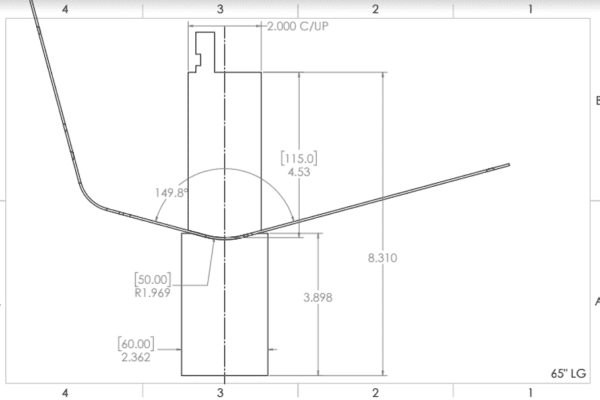
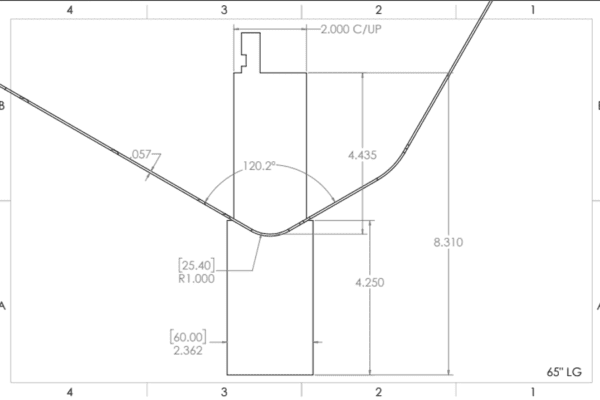
Bump Forming vs. Dedicated Radius Tooling: Quick Comparison
| Factor | Bump Forming | Dedicated Radius Tooling |
|---|---|---|
| Tooling Investment | Usually lower because existing press brake tooling may be used | Higher because tooling may need to be purchased or manufactured |
| Prototype & Low Volume | Excellent fit | Tooling cost may be difficult to justify |
| Setup & Programming | More involved | Generally simpler once tooling and process are established |
| Cycle Time | Multiple press brake hits required | Typically fewer forming operations |
| Radius Flexibility | High; programming can be changed for different radii | Tooling is generally more specific to the required geometry |
| Finished Profile | Slight faceting may be visible depending on bend spacing | Can provide a smoother, more consistent radius |
| Repeat Production | Practical for many low-volume jobs | Can become more efficient as production quantities increase |
What Makes a Part a Good Candidate for Bump Forming?
Bump forming is particularly useful when a design has several of these characteristics:
- Prototype or low-volume production quantities
- A large radius that would otherwise require specialized tooling
- Geometry that is accessible to standard press brake tooling
- A material that can tolerate repeated incremental bending
- A design that can accept slight faceting between individual bends
- A project where avoiding dedicated tooling can reduce cost or lead time
How Smooth Is a Bump-Formed Radius?
A bump-formed curve is actually made from a series of small straight bend segments rather than one continuous rolled curve. The closer the individual bends are positioned, the more closely the finished profile approximates a smooth radius.
However, decreasing the spacing also increases the number of press brake hits required. The goal is therefore to find the right balance between surface smoothness, dimensional requirements, forming time, and part cost.
How Material and Springback Affect Bump Forming
Material type and thickness have a significant effect on bump forming. Different materials respond differently to bending and springback, so the press brake program may need to compensate for how the selected material behaves after forming pressure is released.
Material condition is especially important when creating large radii because the cumulative effect of many small bends determines the final profile. The same programmed bend sequence should not automatically be expected to produce identical results in aluminum, stainless steel, and cold-rolled steel.
Tips for Designers: Optimizing Your Design for Bump Forming
- Clearly define the required radius. Identify which dimensions and portions of the curved profile are functionally critical so the fabricator understands what needs to be controlled.
- Avoid unnecessarily tight profile tolerances. Bump forming is highly useful for large-radius geometry, but the process inherently creates a curve through multiple individual bends.
- Consider the material and thickness. Material ductility, thickness, bend direction, and springback can all influence the achievable profile.
- Keep the geometry accessible. Nearby flanges, hardware, formed features, or other geometry can interfere with press brake tooling as the part progresses through multiple bends.
- Discuss cosmetic requirements. If the finished radius is highly visible and must appear completely smooth, let your fabricator know. A different forming method or tighter bump spacing may be appropriate.
For prototypes and low-volume sheet metal parts, bump forming can provide an effective way to create large-radius geometry without immediately investing in dedicated tooling. The best approach ultimately depends on the radius, material, tolerance, appearance, quantity, and overall part geometry.
Contact us to learn about our full capabilities in metal fabrication!
Recommended Default Sheet Metal Tolerances
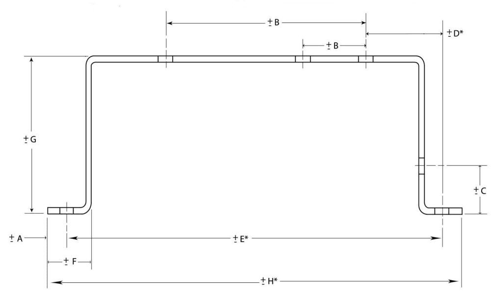
| DIM | Tolerance (MM) | Tolerance (Inches) | Description |
| A | ± 0.13 | ± 0.005 | Sheared Edge to Hole |
| B | ± 0.13 | ± 0.005 | 2 Holes on One Surface |
| C | ± 0.25 | ± 0.010 | Formed Edge to Hole |
| D* | ± 0.76 | ± 0.030 | Holes Across 2 Bends |
| E* | ± 0.76 | ± 0.030 | Holes Across 4 Bends |
| F | ± 0.25 | ± 0.010 | Sheared Edge to Bend |
| G | ± 0.38 | ± 0.015 | Across 2 Bends |
| H* | ± 0.76 | ± 0.030 | Formed Part |
Noted dimensions are to be taken while the part is in a restrained condition. Noted dimensions are for parts within a 12” envelope.
* Dimensions D, E and H are not recommended forms of dimensioning
These tolerances are recommended and best practices. We can obtain tighter tolerances (depending on part geometry/ construction), contact us for more information


