
Last updated on August 28th, 2026 at 09:28 am
EMI/RFI shielding helps protect electronic components and systems from unwanted electromagnetic energy that can interfere with their operation, signal integrity, or reliability.
For a fabricated sheet metal enclosure, shielding performance is not determined by material alone. Seams, ventilation openings, connector cutouts, doors, removable covers, cable penetrations, coatings, and electrical continuity between mating surfaces can all affect the performance of the finished assembly.
That means EMI/RFI shielding should be considered as part of the complete enclosure design rather than simply choosing a conductive metal and assuming the enclosure will provide the required shielding.
What Is EMI/RFI Shielding?
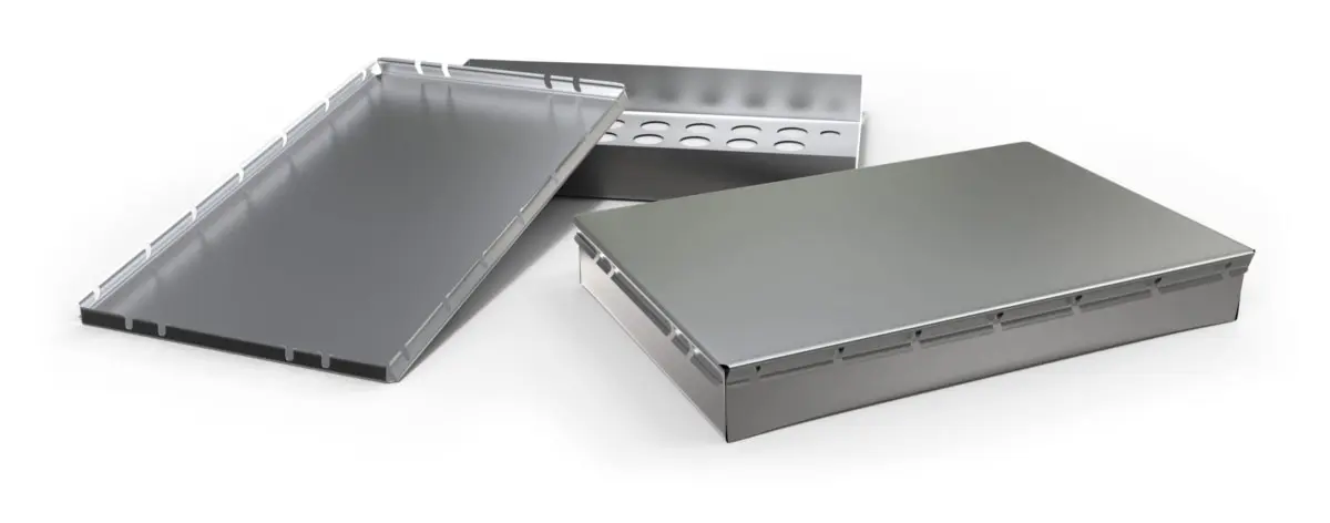
EMI stands for electromagnetic interference, the broader term for unwanted electromagnetic energy that disrupts an electronic device, circuit, or system.
RFI stands for radio frequency interference and generally refers to electromagnetic interference occurring within the radio-frequency portion of the electromagnetic spectrum.
Although EMI and RFI are sometimes discussed separately, many of the same sheet metal enclosure design principles apply to both.
Conductive metal shields and enclosures can help reflect, absorb, or redirect electromagnetic energy. However, the shielding effectiveness of the finished product depends on the complete system, including the frequency range, enclosure geometry, material, seams, openings, conductive joints, grounding or bonding strategy, and other components.
EMI/RFI shielding is commonly used in electronics, communications equipment, aerospace and defense systems, medical equipment, industrial controls, test equipment, robotics, automotive electronics, and other applications where unwanted electromagnetic energy can interfere with operation or signal integrity.
What Affects EMI/RFI Shielding in a Sheet Metal Enclosure?
Material selection matters, but it is only one part of the shielding system.
When designing a fabricated shield or enclosure, engineers should consider:
- Shield material and thickness
- Frequency range of concern
- Seams and joints
- Doors and removable covers
- Ventilation openings
- Connector cutouts
- Cable penetrations
- Electrical continuity between mating components
- Grounding and bonding surfaces
- Coatings and finishes
- Hardware and fastener placement
- Conductive gaskets or other interface components, when required
A shield fabricated from highly conductive material can still perform poorly if large openings, long seams, poorly bonded panels, or insulating coatings interrupt the intended conductive enclosure.
Material Selection for EMI/RFI Shielding
The appropriate shielding material depends on the electrical requirements of the application as well as weight, corrosion resistance, strength, formability, availability, finishing requirements, and cost.
There is no universal ranking of sheet metals for EMI/RFI shielding because performance also depends on frequency, field type, material thickness, enclosure geometry, seams, and the construction of the finished assembly.
| Material | Why It May Be Used | Fabrication Considerations |
|---|---|---|
| Copper | Very high electrical conductivity | Higher material cost and greater density than aluminum |
| Aluminum | Lightweight, conductive, corrosion resistant, and formable | Surface oxide and finishing should be considered where conductive contact between components is required |
| Steel | Strong, economical, and useful in many enclosure applications | Corrosion protection or another finish may be required depending on the environment |
| Tin-Plated Steel | Combines a steel substrate with a plated surface | Exact material and plating specification should be identified on the drawing |
| Stainless Steel | Excellent corrosion resistance and durability | Lower electrical conductivity than copper or aluminum and generally requires more forming force |
| Specialty High-Permeability Alloys | May be used for certain low-frequency magnetic-field shielding applications | Highly application-specific and may require specialized material handling or processing |
Low-frequency magnetic-field shielding can be significantly different from shielding higher-frequency electromagnetic interference. Applications involving specialty high-permeability materials should be engineered around the specific frequency, field strength, geometry, and shielding requirement rather than treated as a standard sheet metal enclosure application.
Why Seams and Joints Matter in EMI/RFI Shielded Enclosures
Most fabricated enclosures are not one continuous piece of metal. They contain seams, removable covers, doors, overlapping flanges, bolted joints, welded joints, hinges, and other interfaces.
Those interfaces can interrupt the conductive path around the enclosure.
For removable covers and panels, shielding performance may be affected by:
- Flange overlap
- Surface flatness
- Fastener location and spacing
- Electrical contact between mating surfaces
- Finish or coating buildup
- Hinge and latch design
- Conductive gasket requirements
If electrical continuity across a seam is critical, identify that requirement during the design stage. Depending on the application, the electrical design may call for bare conductive mating surfaces, conductive gaskets, finger stock, specific hardware, welding, or another method of maintaining continuity.
Design Openings Around the Required Shielding Performance
Most electronic enclosures need openings. Ventilation, fans, connectors, switches, displays, controls, and cable entries all require interruptions in the sheet metal enclosure.
Those openings should be considered during the EMI/RFI design process rather than added after the enclosure geometry is complete.
Common enclosure openings include:
- Ventilation holes
- Louvers
- Perforated patterns
- Fan cutouts
- Connector openings
- Cable entries
- Display windows
- Switch and control openings
For electromagnetic shielding, the geometry of an opening matters. A long continuous slot can behave differently from an array of smaller openings even when the total open area is similar.
When ventilation and shielding are both important, engineers should evaluate the required airflow along with the frequency range and shielding requirement before finalizing the opening pattern.
Connector and Cable Penetrations Need Special Attention
Connectors and cables create another path through an otherwise conductive enclosure.
The electrical designer should define the required connector shielding, cable termination, filtering, and grounding strategy. From a fabrication standpoint, ASM needs accurate information about:
- Connector cutout geometry
- Mounting-hole locations
- Connector orientation
- Required conductive contact surfaces
- Masking requirements
- Grounding or bonding locations
Providing the mating connector or complete manufacturer part number can also help confirm that the fabricated cutout and mounting pattern match the intended component.
Grounding and Bonding Surfaces in Sheet Metal Enclosures
Multi-piece shields and enclosures may require electrical continuity between covers, panels, chassis sections, doors, or other fabricated components.
The electrical designer should determine where conductive bonding or grounding is required. Those requirements should then be communicated clearly on the fabrication drawing.
Examples of features that may require special consideration include:
- Ground studs
- Grounding hardware
- Bare-metal contact areas
- Masked surfaces
- Conductive mating flanges
- Bonding locations between enclosure components
Defining these areas before fabrication allows hardware insertion, finishing, masking, and assembly operations to be planned around the electrical requirements of the enclosure.
Finishing Can Affect Electrical Continuity
Finishing should be considered carefully on components that rely on conductive contact between mating surfaces.
Powder coating, for example, creates an electrically insulating coating. If powder coat is applied between two surfaces that need conductive contact, it may interrupt the intended electrical path.
Anodized aluminum surfaces also behave differently from bare conductive aluminum at electrical contact points.
Depending on the design, critical areas may need to be masked during finishing. Common examples include:
- Grounding points
- Bonding surfaces
- Conductive mating flanges
- Threaded electrical contact points
- Selected hardware interfaces
Plating or conversion coatings may also be specified when the application requires a particular combination of corrosion protection and electrical surface characteristics.
The required finish and any conductive or masked areas should be clearly identified on the drawing rather than determined after the parts have already been fabricated.
Design Removable Covers Around Shielding Requirements
Removable covers create a unique challenge because the enclosure needs to open for assembly or service while still maintaining the required interface when closed.
When designing a removable EMI/RFI cover, consider:
- Amount of flange overlap
- Cover flatness
- Fastener type
- Fastener placement
- Conductive contact between the cover and enclosure
- Finish on mating surfaces
- Gasket requirements
- Repeated removal and installation
There is no universal fastener spacing or flange dimension that guarantees shielding performance. Those requirements depend on the enclosure design, frequency range, shielding target, gasket system, and other electrical requirements.
What Should You Include in an EMI/RFI Shield RFQ?
The more information ASM receives about the complete enclosure and its functional requirements, the easier it is for us to review the fabrication requirements before production.
When possible, include:
- 3D model
- 2D fabrication drawing
- Material and thickness
- Complete mating enclosure or assembly
- Connector manufacturer and part numbers
- Ventilation requirements
- Hardware manufacturer and part numbers
- Grounding and bonding locations
- Surfaces requiring conductive contact
- Masking requirements
- Finish or plating specification
- Conductive gasket requirements, when applicable
- Required shielding effectiveness and frequency range, when specified
- Applicable EMC or customer test specification, when required
If several fabricated components make up the shielded enclosure, submit them together whenever possible. This allows ASM to review seams, mating surfaces, cover geometry, hardware, and other assembly relationships in context rather than treating each component as an unrelated sheet metal part.
Who Determines the Required EMI/RFI Shielding Performance?
ASM’s role is to manufacture the sheet metal shield or enclosure to the customer’s design and fabrication requirements.
The product designer, electrical engineer, or EMC engineer should define the required shielding performance, frequency range, grounding and bonding strategy, connector requirements, and applicable system-level compliance requirements.
If a shield must achieve a specific attenuation level over a defined frequency range, include that requirement with the RFQ and drawing package.
The performance of the finished shielding system ultimately depends on the complete product, including components outside the fabricated sheet metal itself, and should be validated using the appropriate EMC test method when required.
ASM’s EMI/RFI Shielding Fabrication Capabilities
Approved Sheet Metal has extensive experience fabricating custom sheet metal shields, covers, enclosures, and assemblies for electronics and other applications where EMI/RFI considerations are part of the product design.
Depending on the component, manufacturing processes may include laser cutting, punching, forming, welding, hardware insertion, and assembly.
ASM works with commonly specified sheet metal materials including aluminum, steel, stainless steel, and copper. Material selection should be based on the electrical, mechanical, environmental, and fabrication requirements of the application.
Depending on the material and design, finishing can also be incorporated into the manufacturing plan. When conductive contact, grounding, or bonding surfaces are required, identify those areas so the finishing and masking requirements can be planned accordingly.
Whether you need a handful of prototype shields or low-volume production quantities, our custom sheet metal fabrication team can review your design for manufacturability and help identify fabrication issues before production.
Looking for custom sheet metal EMI/RFI shields for your next project? Request a quote today!


