Last updated on January 22nd, 2026 at 08:46 am
Sheet metal forming is a core part of custom sheet metal fabrication. Most fabricated parts require bending, which permanently stretches material in the bend region and changes the final part length.
When a sheet metal part is bent, the metal inside the bend compresses while the outside stretches. Accounting for this material behavior is critical when designing flat patterns that need to form accurately.
Below are the five most important sheet metal design formulas used to calculate bend behavior. These formulas help ensure proper fit, predictable forming, and consistent results in production.
Why Sheet Metal Design Formulas Matter
Sheet metal design formulas account for how material stretches and compresses during bending. Without these calculations, flat patterns will not form correctly, leading to dimensional errors, poor fit, and rework. Using the correct formulas early in the design process helps ensure accurate parts and efficient fabrication.
5 Important Sheet Metal Design Formulas
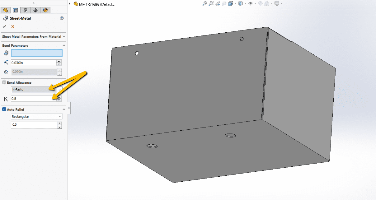
#1 K-Factor
The K-Factor is a crucial parameter used to determine how much a given material will stretch or compress during bending. The K-Factor is used to calculate the Bend Deduction and Bend Allowance (formulas #2 and #3), which in turn are used to determine the correct size of the unfolded flat pattern for the part.
Understanding the K-Factor
The K-Factor represents the ratio of the location of the neutral axis to the material thickness. The neutral axis is the theoretical line within the material that experiences no compression or tension during bending.
where:
- BA is the bend allowance
- B< is the bend angle
- IR is the inside radius
- MT is the material thickness
The K-Factor is a dimensionless value and typically ranges between 0 and 0.5 for most sheet metal materials and bending operations. The value depends on several factors, including material type, thickness, and bend radius.
K = 0: The neutral axis is located at the outer surface of the bend, which is unrealistic for practical purposes.
K = 0.5: The neutral axis is located exactly halfway through the thickness of the material, which typically occurs with very soft materials or very large bend radii.
Practical Range: For most practical applications, the K-Factor ranges between 0.3 and 0.5.
At Approved Sheet Metal, we most often use the K-Factor to compute bend deductions for non 90 degree bends such as offsets and hems.
#2 Bend Allowance
The Bend Allowance (BA) is the length of the neutral axis in a bend. If you add the bend allowance to the leg lengths of the part, you will get the required length of the flat pattern.
Bend allowance is typically used when calculating flat patterns directly from leg lengths.
Why Bend Allowance is Important
- Accurate Dimensions: Without accounting for the Bend Allowance, the final part dimensions would be incorrect. The Bend Allowance ensures that when the part is bent, it will match the specified dimensions in the design.
- Material Utilization: Properly calculating Bend Allowance helps in optimizing the use of material, reducing waste, and controlling costs. It ensures that the cut piece of sheet metal will be the correct size after bending.
- Fit and Assembly: Parts that are bent to incorrect dimensions may not fit together properly, leading to assembly issues. By incorporating the correct Bend Allowance, parts will fit together as intended.
- Stress and Structural Integrity: Incorrect bend calculations can result in too much or too little material in the bend area, potentially weakening the part or causing it to fail under stress.
How Bend Allowance is Calculated
Bend allowance depends on several factors, including the material thickness (T), the bend radius (R), the bend angle (A), and the K-factor (K), which accounts for the location of the neutral axis.
Computing the bend allowance is much like calculating the arc length on a circle. First, determine the radius of the neutral axis, starting with the inside bend radius and adding an adjustment using the K-Factor and the material thickness. Then, multiply by the bend angle in radians.
The formula for bend allowance (BA) is:
where:
- MT is the material thickness
- B < is the bend angle
- IR is the inside radius
- K is the K-factor, which typically ranges between 0.3 and 0.5 for most metals and bending operations
#3 Bend Deduction
Bend Deduction (BD) is the amount you must subtract from the desired part size to get the correct length of the flat pattern, in order to compensate for the amount the material will stretch during bending.
We use the Bend Deduction formula every day at Approved Sheet Metal to compute our standard sheet metal bend gains chart. This chart serves as a handy reference for bend deductions with a variety of materials and thicknesses, and is a valuable resource for understanding how sheet metal stretches when bent.
Why Bend Deduction is Important
- Accurate Flat Pattern Layout: Bend Deduction ensures that the flat pattern is dimensioned correctly so that, after bending, the part matches the desired final dimensions. This is crucial for precision and proper fit in assembly.
- Consistency in Fabrication: By using Bend Deduction, fabricators can consistently produce parts that meet design specifications, leading to fewer errors and rework.
- Material Efficiency: Properly calculated Bend Deduction helps in minimizing material waste, ensuring efficient use of resources.
- Ease of Manufacturing: Bend Deduction simplifies the calculation process for the flat pattern layout, making it easier for fabricators to cut and bend the sheet metal accurately.
How Bend Deduction is Calculated
Bend Deduction depends on the bend angle (A), the material thickness (T), the inside bend radius (R), and the K-factor (K). It is derived from the relationship between the Bend Allowance and the initial flat length. The formula for Bend Deduction (BD) is:
where:
- MT is the material thickness
- B < is the bend angle
- IR is the inside radius
- K is the K-factor, which typically ranges between 0.3 and 0.5 for most metals and bending operations
#4 Inside Setback
When designing two mating flanges, it is important to keep in mind the curvature of the bends. For example, a 90° bend is not truly square – it has a radius, and a mating flange cannot sit flush with both interior edges of the bend. As such, a mating flange must be “set back” by a specified amount to ensure a proper fit when the flanges are assembled. This amount is called the Inside Setback (SB).
Why Inside Setback is Important
- Accurate Flat Pattern Layout: Inside Setback ensures that the flat pattern is dimensioned correctly, allowing for precise bending and resulting in a part that matches the desired final dimensions.
- Proper Fit and Assembly: Accurately calculating Inside Setback ensures that bent parts fit together correctly during assembly, avoiding issues that could arise from inaccurate bends.
Understanding Inside Setback
Inside Setback is based on the material thickness (T) and the inside bend radius (R). It is used in conjunction with the bend angle (A) to determine the precise length of the flat pattern. The inside setback does not depend on the material type. It depends only on bend geometry, including bend angle and inside radius.
The formula for Inside Setback is:
where:
- MT is the material thickness
- B < is the bend angle
- IR is the inside radius
#5 Outside Setback
Like the Inside Setback, the Outside Setback (OSSB) is an important consideration when designing mating flanges. Since bends are not perfect squares, but are instead rounded, a mating flange cannot sit flush with both exterior edges of a bend without creating an undesirable overhang. Outside Setback determines how much a mating flange must be “set back” to avoid such overhang.
Why Outside Setback is Important
- Accurate Flat Pattern Layout: Outside Setback ensures that the flat pattern is dimensioned correctly, leading to precise bends and a part that meets the desired specifications.
- Proper Fit and Assembly: Accurate Outside Setback calculations ensure that bent parts fit together correctly during assembly, avoiding issues related to misalignment or improper fit.
Understanding Outside Setback
Outside Setback (OSSB) depends on the material thickness (T), the inside bend radius (R), and the bend angle (A). It is used to determine the distance from the outside edge of the bend to the mold line intersection. Like the Inside Setback, the Outside Setback does not depend on the material, only on the geometry of the bend.
The formula for Outside Setback is:
where:
- MT is the material thickness
- B < is the bend angle
- IR is the inside radius
Practical Applications in Custom Sheet Metal Fabrication
Using these design formulas helps ensure that sheet metal parts form correctly and meet dimensional requirements. While the calculations can seem complex, experienced fabricators apply them daily to produce accurate parts.
If you have questions about applying these formulas to your design or need help validating a flat pattern, our team can review your files before fabrication begins.
Request a quote to work with us today.