
Last updated on August 31st, 2026 at 11:11 am
Welded sheet metal assemblies can combine multiple laser-cut and formed components into larger enclosures, frames, brackets, cabinets, and other fabricated assemblies.

But welding also introduces heat, shrinkage, and dimensional variation that need to be considered during design. Joint geometry, material, thickness, weld access, cosmetic requirements, production quantity, and the required performance of the finished assembly can all influence the best manufacturing approach.
At Approved Sheet Metal, we use multiple welding processes and assembly techniques depending on the requirements of each custom sheet metal weldment.
Sheet Metal Welding Methods for Fabricated Assemblies
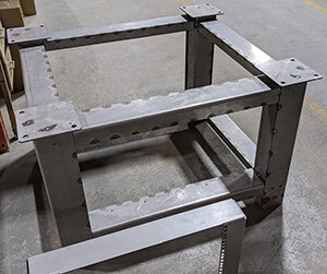
A weldment is an assembly created by permanently joining multiple fabricated components through welding.
MIG and TIG welding are commonly used for custom sheet metal assemblies, but they are not the only options. Depending on the joint design and application, resistance spot welding, resistance seam welding, or plug welding may provide a better manufacturing approach.
Resistance Spot Welding
Resistance spot welding joins overlapping sheets by clamping them between two electrodes and passing electrical current through the workpieces.
Electrical resistance generates heat at the interface between the sheets, creating a localized weld nugget that joins the materials.
Spot welding can be fast and repeatable when the part is designed appropriately. Important design considerations include:
- Access for electrodes on both sides of the joint
- Material type and thickness
- Amount of overlap
- Spot weld location and spacing
- Proximity to bends, edges, and other features
- Required strength and appearance
Spot welding can be particularly useful when overlapping sheet metal components need multiple localized welds without a continuous weld bead.
Resistance Seam Welding
Resistance seam welding uses rotating wheel electrodes to create a series of overlapping resistance welds along a joint between sheet metal components.
Depending on the material, joint design, equipment, and process settings, the overlapping welds can create a continuous sealed seam.
This can make seam welding useful for certain fabricated assemblies where a continuous joint is required without using a conventional MIG or TIG weld bead.
If an assembly must be watertight, airtight, or meet a specific leak requirement, identify that requirement on the drawing or purchase order along with the required inspection or test method. The welding process alone should not be assumed to guarantee a leak-tight assembly.
Feasibility also depends on the material thickness, material type, joint geometry, required weld, and available machine access.
Plug Welding
A plug weld joins overlapping components by welding through a hole in the outer sheet to the material underneath.
The weld fills the opening and creates a localized connection between the two components. Slot welds use the same general concept with an elongated opening rather than a round hole.
Plug and slot welds can be useful when:
- Components overlap
- Direct access to an edge joint is limited
- A localized welded connection is preferred over a continuous seam
- The assembly geometry makes another weld joint difficult to access
The hole or slot geometry, weld size, spacing, and quantity should be based on the requirements of the assembly rather than treated as universal dimensions.
MIG and TIG Welding
MIG and TIG welding remain important processes for custom sheet metal weldments.
The appropriate process depends on factors such as material, thickness, joint configuration, required weld size, production quantity, accessibility, cosmetic requirements, and allowable heat input.
Rather than selecting a welding process based on one factor alone, the complete assembly should be evaluated to determine the most practical method for producing the required joint.
Weldment Best Practices at Approved Sheet Metal
Producing an accurate sheet metal weldment requires more than making each individual weld. The complete manufacturing sequence should account for fit-up, heat input, shrinkage, fixturing, and the dimensions that must be maintained after welding.
Control Heat Input and Welding Sequence
Welding introduces localized heat into the assembly. As the weld and surrounding material cool, shrinkage can cause bowing, twisting, oil-canning, or other dimensional changes.
Heat input can be managed through the welding process, weld size, sequence, joint design, fixturing, and the amount of welding required.
Where a continuous weld is not functionally required, intermittent welds may sometimes reduce total heat input. Weld sequence can also be planned to distribute heat and shrinkage rather than concentrating welding in one area of the assembly.
Use Alignment Features When Appropriate
Features designed directly into laser-cut components can help locate parts before and during welding.
Depending on the assembly, these can include:
- Tabs and slots
- Locating features
- Temporary Cleco holes
- Interlocking components
These features can improve repeatability, help establish orientation, and reduce the amount of manual positioning required during fit-up.
They should still be designed with appropriate clearance for the cutting, forming, and assembly processes.
Use Fixtures to Control Fit-Up
Custom welding fixtures can locate components and help resist movement caused by fit-up variation and weld shrinkage.
Fixtures do not eliminate welding distortion, but they can help control the assembly while critical joints are being welded.
Fixture strategy becomes increasingly important for larger weldments, assemblies with multiple components, and parts with critical post-weld dimensions.
Welding Design and Engineering Best Practices
Designing a sheet metal weldment requires balancing structural requirements, manufacturability, dimensional control, appearance, and cost.
1. Choose the Right Weld Joint
The joint configuration affects weld access, fit-up, heat input, strength, and the amount of finishing that may be required.
Common sheet metal joint configurations include:
- Butt joints: Two components meet along their edges.
- Lap joints: One sheet overlaps another, making the geometry suitable for processes such as spot, seam, plug, or conventional welding depending on the design.
- Corner joints: Components meet at or near a corner and are common in boxes, enclosures, and frames.
- T-joints: One component intersects another, typically near a 90-degree angle.
- Edge joints: Adjacent edges are joined together where the design and load requirements make the configuration appropriate.
Fillet welds are commonly used with lap, corner, and T-joint configurations. Plug and slot welds provide another option for joining overlapping sheet metal components.
2. Design Tabs and Slots for Better Fit-Up
Tabs and slots can make complex weldments easier to assemble by helping components locate relative to one another before welding.
Well-designed locating features can:
- Establish component orientation
- Reduce manual measurement during fit-up
- Help prevent components from being assembled incorrectly
- Improve repeatability between assemblies
- Reduce dependence on complex fixturing in some designs
Tabs and slots should not be designed as zero-clearance features. The required fit should account for cutting tolerances, material thickness, forming variation, and the needs of the welding process.
3. Plan for Weld Access
A weld may look straightforward in CAD but become difficult to produce after surrounding components have been formed or assembled.
Before finalizing a weldment, consider whether the welding torch, resistance-welding electrodes, fixture, and operator can physically reach each required joint.
Potential access problems include:
- Welds deep inside enclosures
- Joints blocked by formed flanges
- Closely spaced internal components
- Return flanges near the weld location
- Joints that become inaccessible after another component is installed
Assembly and welding sequence should be considered during design rather than after all of the individual components have already been fabricated.
4. Specify Only the Welding the Part Requires
More welding is not automatically better.
Unnecessary weld length can add heat, distortion, labor, finishing time, and cost to an assembly.
If a continuous weld is required for strength, sealing, appearance, or another functional reason, specify it. If the design permits intermittent welds or localized connections, those alternatives may reduce heat input and manufacturing time.
The engineer should define the functional weld requirements while allowing the fabricator to review the most practical way to produce them.
5. Define Weld Appearance and Finishing Requirements
Functional and cosmetic welds can require very different amounts of post-weld finishing.
A note such as "weld and grind smooth" can be interpreted differently depending on the application. If appearance matters, identify the surfaces that are cosmetic and define the required finished condition.
Depending on the project, requirements may include:
- Welds left as welded
- Welds cleaned or dressed
- Welds blended into surrounding surfaces
- Specific cosmetic surfaces
- Continuous seams
- Leak testing
- Post-weld finishing requirements
Clearly defining these requirements during quoting helps avoid unnecessary grinding and makes it easier to establish the correct manufacturing process.
6. Account for Welding When Applying Tolerances
Welding introduces localized heating and shrinkage, so dimensions across a welded assembly can behave differently from dimensions on an individual laser-cut or formed component.
For weldments with critical dimensional requirements, clearly identify:
- Critical mating dimensions
- Datum surfaces
- Hole patterns that must align after welding
- Overall dimensions that affect assembly
- Flatness or squareness requirements where functionally necessary
- Dimensions that must be verified after welding
Avoid applying unnecessarily tight tolerances to every dimension of a weldment. Instead, identify the dimensions that control fit and function so the welding and inspection strategy can be developed around them.
7. Consider the Final Finish
The required finish can affect how the weldment should be designed, welded, and cleaned.
Powder coating, plating, anodizing, passivation, and other finishing processes may have different requirements for weld cleanup, surface preparation, masking, and cosmetic appearance.
On welded aluminum parts that will be anodized, the weld metal, heat-affected areas, and surrounding base material may not anodize to exactly the same appearance. If cosmetic uniformity is important, discuss the requirement before manufacturing begins.
Welding Isn't Always the Best Assembly Method
Some sheet metal assemblies can be produced more efficiently using rivets, self-clinching hardware, screws, tabs, or other mechanical fastening methods.
The best assembly method depends on strength, serviceability, appearance, sealing requirements, material, quantity, and whether the assembly ever needs to be taken apart.
If welding is not functionally required, evaluating welding versus mechanical fastening during the design stage can sometimes simplify production.
Sheet Metal Weldment Design Checklist
- Is the selected welding process appropriate for the material and thickness?
- Can the welding equipment physically access every joint?
- Can tabs, slots, or other locating features simplify fit-up?
- Are continuous welds required, or can some joints be intermittent?
- Have critical post-weld dimensions been identified?
- Has potential heat distortion been considered?
- Are cosmetic weld surfaces clearly identified?
- Are grinding or weld-blending requirements defined?
- If the assembly must be leak-tight, is the required test specified?
- Has the final finishing process been considered?
- Could mechanical fastening simplify any portion of the assembly?
Send the Complete Weldment for DFM Review
For multi-component weldments, send the complete 3D assembly along with fully dimensioned drawings and applicable weld requirements.
Approved Sheet Metal can review the design for joint access, component fit-up, alignment features, fixturing, welding sequence, dimensional requirements, and finishing considerations before production begins.
Sheet Metal Part Design for Manufacturing Tip
CORNERS AND WELDING
Proper technique on corners that need to be welded is necessary to reduce cost and increase the overall strength of the corners. Approved Sheet Metal will always reprogram corners that need to be welded to ensure customers receive the best possible welds.


