Last updated on August 28th, 2026 at 09:54 am
PEM® transitioned its legacy TD™ self-clinching cable tie-mount product line to the stainless steel TDS™ product family in 2022.
That transition is no longer new, but it still matters because older CAD models, engineering drawings, and bills of materials may continue to call out discontinued TD hardware.
If you encounter a legacy TD part number, don't simply change “TD” to “TDS” and assume the rest of the design is correct. Engineers should verify the current PEM® specification for the exact replacement hardware, including mounting-hole requirements, panel thickness, panel hardness, installation requirements, and mechanical performance.
Here's what sheet metal engineers and buyers should know when updating an older design.
What Are PEM TDS Cable Tie-Mounts?
PEM TDS hardware is a family of self-clinching cable tie-mounts, also commonly called tie-downs. They provide an integrated attachment point for securing wires and cable bundles to sheet metal enclosures, chassis, panels, and other fabricated assemblies.
Instead of adding a separate screw-mounted or adhesive-backed cable anchor, the self-clinching feature allows the tie-mount to become mechanically retained in the sheet metal panel during hardware insertion.
Potential advantages include:
- Permanent installation without separate mounting screws or adhesive
- A low-profile installation that can keep the opposite side of the panel unobstructed
- A repeatable attachment location for wire and cable management
- Integration directly into the fabricated sheet metal component
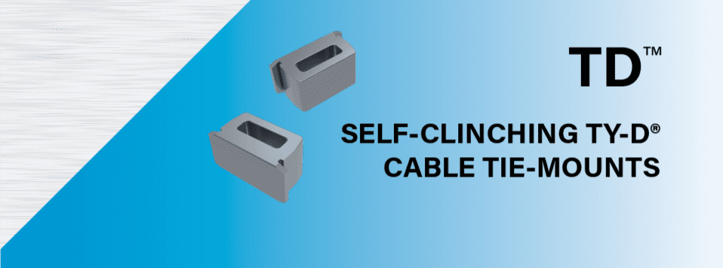
The legacy TD family used sintered steel construction, while the successor TDS family uses stainless steel. The change in material should not be interpreted to mean that every TDS fastener is automatically stronger than its legacy counterpart.
If the tie-mount has a specific mechanical load requirement, use the published PEM performance data for the exact TDS part number.
Why Legacy TD Callouts Still Matter
Older products can remain in production for years, which means discontinued hardware can continue appearing on:
- Legacy 3D CAD models
- 2D fabrication drawings
- Bills of materials
- Assembly drawings
- Customer specifications
- Previously released production packages
When one of these designs comes back into production, the hardware callout should be reviewed before the fabrication order is released.
PEM introduced the TDS family as the successor to the legacy TD product family, but engineers should verify the current manufacturer data rather than assuming interchangeability based only on similar naming or dimensions.
Legacy TD and Current TDS Hardware
Legacy TD part numbers previously used in designs included:
- TD-175-12X
- TD-175-12ZI
- TD-40-4ZI
- TD-60-4ZI
- TD-60-6ZI
TDS family part numbers include:
- TDS-175-12
- TDS-175-12ZI
- TDS-40-4
- TDS-40-4ZI
- TDS-60-6
- TDS-60-6ZI
Do not assume every legacy TD number maps directly to a TDS number without reviewing the current PEM documentation for the specific application.
| Design Consideration | Legacy TD | TDS |
|---|---|---|
| Product Status | Legacy/discontinued product family | Successor product family |
| Material | Sintered steel | Stainless steel |
| Mounting Hole | Verify legacy drawing and manufacturer data | Verify current PEM specification |
| Panel Thickness | Verify applicable requirement | Verify current PEM specification |
| Panel Hardness | Verify applicable requirement | Verify current PEM specification |
| Mechanical Performance | Use applicable legacy data | Use published TDS performance data |
| Finishing Sequence | Application dependent | Confirm with hardware and finishing requirements |
How to Update a Legacy TD Design
If an existing part still specifies TD hardware, review the complete design rather than changing only the BOM.
1. Update CAD Models, Drawings, and BOMs
Where appropriate, update:
- 3D CAD models
- 2D fabrication drawings
- Assembly drawings
- Bills of materials
- Hardware notes
- Purchase specifications
The drawing and BOM should identify the exact manufacturer and part number required rather than simply stating “PEM tie-down” or “TDS hardware.”
2. Verify the Mounting Hole
Self-clinching hardware depends on a properly sized mounting hole.
Do not assume the hole shown on a legacy TD drawing is automatically correct for a TDS fastener. Compare the existing design to PEM's current mounting-hole specification for the exact part number.
Hole geometry is particularly important with self-clinching hardware because an oversized, undersized, improperly shaped, or poorly located hole can affect installation and retention.
3. Verify Sheet Thickness and Panel Hardness
Self-clinching hardware works by displacing panel material into features in the fastener during installation. The sheet therefore needs to meet the manufacturer's specified material thickness and hardness requirements.
Verify:
- Sheet material
- Material temper or condition where relevant
- Sheet thickness
- Maximum panel hardness
- Minimum edge distance
- Installation requirements
Do not assume that a stainless steel self-clinching fastener can be installed successfully into every stainless steel sheet material simply because both components are stainless.
Use the current PEM specification for the exact fastener and panel combination.
Consider Material Compatibility and Galvanic Corrosion
TDS hardware is stainless steel, so material compatibility should be considered when it is installed in another metal such as aluminum.
When stainless hardware and aluminum are electrically connected and exposed to moisture or another electrolyte, galvanic corrosion may become a design consideration.
The actual risk depends on factors including:
- Service environment
- Moisture exposure
- Relative exposed surface areas
- Coating and pretreatment system
- Assembly geometry
- Required service life
For indoor electronics enclosures in controlled environments, the risk may be very different from an outdoor assembly exposed to salt, humidity, or frequent condensation.
Material compatibility should therefore be evaluated as part of the complete assembly rather than based only on the hardware material.
Consider the Finishing and Hardware Installation Sequence
The hardware installation sequence depends on the sheet material, fastener, finish, electrical requirements, and cosmetic requirements.
Do not assume TDS hardware should always be installed before or after a particular finishing process.
If hardware is being installed in a part that will receive:
- Powder coating
- Wet paint
- Anodizing
- Chromate conversion coating
- Plating
- Another chemical or protective finish
confirm that the planned installation sequence is compatible with both the hardware manufacturer's requirements and the finishing specification.
For coated assemblies, also determine whether the TDS hardware should remain bare, receive coating, or be masked.
Masking may be important when the hardware provides an electrical contact point, when coating buildup could interfere with a cable tie, or when the cosmetic appearance of the hardware matters.
Verify Mechanical Performance
The move from sintered steel TD hardware to stainless steel TDS hardware should not be treated as proof that the newer fastener automatically has greater mechanical strength.
If the tie-down carries a meaningful load or is used in an application where cable retention is critical, verify the manufacturer's published mechanical performance for the specific TDS fastener.
Consider the actual application requirements, including:
- Cable bundle weight
- Pull direction
- Vibration
- Shock
- Temperature
- Environmental exposure
- Required service life
The fastener, sheet material, installation, and cable tie all contribute to the performance of the completed attachment.
Don't Assume Alternate Hardware Is a Drop-In Replacement
Hardware availability can affect the lead time of any custom sheet metal project, especially when a design specifies an exact manufacturer part number.
If a specific TDS fastener is unavailable, an alternate cable tie-mount may be worth evaluating, but it should be treated as an engineering substitution rather than an automatic drop-in replacement.
An alternate fastener may have different:
- Mounting-hole requirements
- Panel-thickness ranges
- Panel-hardness limitations
- Installation forces
- Dimensions
- Material
- Finish
- Mechanical performance
Any substitution should therefore be reviewed and approved before the drawing, BOM, or production process is changed.
What ASM Needs on the RFQ
If your design uses PEM TDS hardware, include the exact manufacturer part number on the drawing or BOM whenever possible.
Also provide:
- 3D CAD model
- Fully dimensioned 2D fabrication drawing
- Sheet material
- Sheet thickness
- Exact hardware part number
- Hardware quantities
- Finish requirements
- Masking requirements
- Any electrical grounding or bonding requirements
- Any hardware-specific inspection or performance requirements
If a legacy drawing still calls out TD hardware, flag it when requesting a quote.
Approved Sheet Metal can help identify obsolete hardware callouts and review the fabrication implications of switching to current hardware. Any hardware substitution or engineering-design change should be reviewed and approved by the customer before production.
Keep Legacy Hardware from Delaying Your Sheet Metal Parts
Hardware is a small part of a fabricated assembly, but an obsolete or incorrectly specified fastener can create unnecessary sourcing delays or force last-minute engineering changes.
For older designs containing PEM TD cable tie-mounts, update the documentation to the appropriate current TDS hardware and verify the manufacturer's latest mounting and installation requirements.
When you're ready to manufacture the part, designing with manufacturability in mind and providing complete hardware callouts helps ASM quote and manufacture the job more efficiently.
Request a quote for your next custom sheet metal fabrication project.
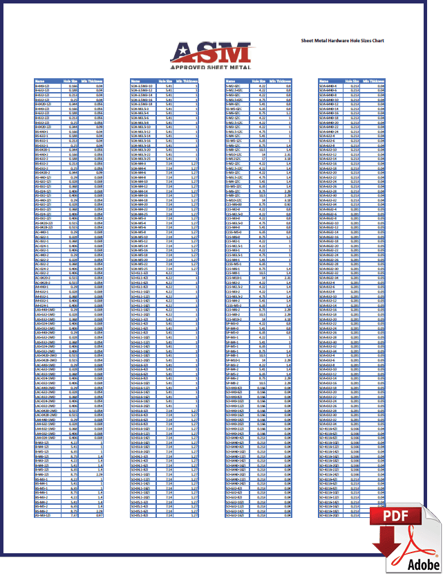
Sheet Metal Hardware Hole Sizes Chart
CHART DOWNLOAD
Hardware hole sizes are the number one thing sheet metal fabricators have to fix before sending a part to the floor. So we have created a referenceable chart for product developers that are designing sheet metal parts. Use this chart to find the correct hole size for the hardware you select.