
Last updated on September 3rd, 2026 at 09:48 am
Fiber laser cutting has become a core process in modern sheet metal fabrication because it combines high cutting speed, flexible geometry, and efficient processing across a wide range of materials and thicknesses.
At Approved Sheet Metal, our AMADA 3kW ENSIS 3015 RI Fiber Laser gives us flexible cutting capability for both flat sheet and tubular or structural profiles, helping support rapid prototyping, low-volume production, and quick-turn fabrication.

What Is a Fiber Laser?
A fiber laser is a solid-state laser cutting system in which the laser beam is generated and delivered through optical fiber.
Compared with older CO2 laser systems, fiber lasers generally offer higher electrical efficiency and can achieve very high cutting speeds, especially in thinner sheet metal.
The technology also works well across many common fabrication materials, making it a strong fit for custom sheet metal parts that may vary widely in geometry, material, thickness, and quantity.
7 Practical Benefits of Fiber Laser Cutting
For engineers and buyers, the value of fiber laser technology is not simply that the machine cuts fast. The bigger advantage is how that speed, flexibility, and automation can improve the overall fabrication process.
- High cutting speed. Fiber laser technology can process thin sheet significantly faster than older laser systems under appropriate conditions. Cutting speed depends on material, thickness, assist gas, geometry, and edge-quality requirements, but higher cutting capacity can help support quick-turn work and low-volume production.
- Flexible part geometry. Because laser cutting does not require dedicated hard tooling for each profile, it is well suited for prototypes, revisions, and low-volume parts with complex contours, holes, slots, notches, cutouts, and etched features.
- Reduced tooling dependence. Many profile changes can be handled through programming rather than custom cutting tools. This makes laser cutting especially useful when engineers expect design revisions or when order quantities do not justify dedicated tooling.
- Process monitoring and automation. Modern fiber laser systems include monitoring and automated functions that help operators manage cutting conditions and maintain consistent processing. These systems can identify certain cutting or piercing problems so they can be corrected rather than allowing the issue to continue through an entire sheet.
- Material flexibility. Our fiber laser can process a broad range of sheet metal materials, including aluminum, stainless steel, carbon steel, copper, and other compatible metals. Practical capability depends on material, thickness, geometry, edge requirements, and the downstream fabrication processes required for the part.
- Clean, consistent cut geometry. Fiber laser cutting can produce clean edges and accurate profiles that may reduce secondary edge cleanup on appropriate materials and thicknesses. Deburring requirements still depend on the material, cut condition, geometry, and the customer's edge requirements.
- Efficient operation. Fiber lasers generally offer higher electrical efficiency and lower laser-source maintenance requirements than older CO2 systems. Cutting operations may still use oxygen, nitrogen, or other assist gases depending on the material and required edge condition.
Flat Sheet and Tube Cutting on One Platform
One of the most useful features of the AMADA ENSIS 3015 RI is its ability to process more than conventional flat sheet.
The rotary-index capability allows the system to cut tubular and structural profiles in addition to flat sheet metal. Depending on the part, this can include round tube, square tube, rectangular tube, channel, and angle.
This is particularly valuable for fabricated frames and assemblies because features such as holes, slots, tabs, notches, and joint geometry can be laser cut before welding or assembly.
By incorporating those features directly into the tube or profile, engineers can often improve part location, repeatability, and fit-up while reducing manual drilling, sawing, or layout work later in the fabrication process.
What Determines Fiber Laser Cutting Speed and Edge Quality?
Laser cutting performance cannot be reduced to one maximum cutting speed or one universal edge-quality specification.
Actual results depend on several variables, including:
- Material type
- Material thickness
- Alloy and material condition
- Assist gas
- Feature size
- Total cut length
- Pierce count
- Part geometry
- Dense cut patterns
- Required edge quality
- Machine and process settings
A thin carbon steel part with a few large profiles may cut very differently from a stainless steel panel containing hundreds of small holes, even if both parts fit within the same sheet size.
Design Guidelines for Fiber Laser-Cut Parts
Good laser-cutting design is less about following universal minimum dimensions and more about avoiding features that create unnecessary cutting time, thermal concentration, instability, or downstream manufacturing problems.
1. Be Careful With Very Small or Fragile Features
Very small holes, narrow slots, thin projections, and narrow webs can become more difficult to process as material thickness increases or geometry becomes more concentrated.
There is no single minimum hole diameter or feature width that applies to every laser-cut part. Feasibility depends on the material, thickness, geometry, process settings, and required quality.
If a very small feature is functionally important, identify it clearly on the drawing so the fabricator can review it during quoting.
2. Do Not Manually Compensate for Laser Kerf
Engineers generally should model holes, slots, and profiles at their required finished dimensions rather than manually offsetting the geometry for laser kerf.
The fabricator's CAM system accounts for the cutting process when generating the machine program.
If a feature requires a particularly tight tolerance or specific edge condition, communicate that requirement on the drawing instead of modifying the CAD geometry to compensate for the expected cut width.
3. Avoid Unnecessarily Dense Cut Patterns
Large arrays of small holes, closely packed slots, perforations, or decorative patterns can increase pierce count, cut length, heat concentration, and machine time.
That does not mean these features cannot be produced. It means they may have a much larger effect on cost and processing time than their physical size suggests.
If the pattern is functional, provide the required geometry. If it is cosmetic or optional, reducing unnecessary features can help simplify the part.
4. Let the Fabricator Manage Cut Sequencing and Part Retention
Laser programming decisions such as cut sequence, piercing strategy, nesting, heat management, and whether temporary retention methods are needed are generally manufacturing decisions.
The engineer should focus on communicating the required finished geometry and functional requirements. The fabricator can determine the cutting strategy that best suits the material, part geometry, and machine.
5. Specify Threads and Hardware Correctly
Conventional internal threads are typically created as a secondary operation rather than cut directly by the sheet laser.
If a hole will be tapped, specify the required thread on the drawing. The fabricator can determine the appropriate pre-tap hole and tapping process.
If the part uses self-clinching hardware, specify the exact manufacturer and part number whenever possible. The required mounting hole depends on the specific hardware family, sheet thickness, material hardness, and installation requirements.
6. Design for Material Utilization, Not the Nest Itself
The fabricator is responsible for nesting parts on the sheet, but part geometry can still affect material utilization.
Features that may reduce yield include:
- Very long or narrow part envelopes
- Large irregular projections
- Dimensions just beyond a commonly available sheet size
- Required material grain orientation
- Cosmetic surface requirements
- Low quantities that cannot be efficiently combined with other work
A relatively small dimensional change can sometimes improve nesting significantly, but those changes should only be made when they do not compromise the part's function.
Laser Cutting Is Often Only the First Step
For many custom sheet metal parts, laser cutting is only one operation in the complete manufacturing process.
The total fabricated part may also require:
- Deburring
- Countersinking
- Tapping
- Forming
- Hardware insertion
- Welding
- Grinding or cosmetic finishing
- Finishing
- Assembly
- Inspection
That is why the fastest possible laser cut does not automatically mean the shortest possible lead time for the complete part. The entire routing, including forming, hardware, welding, finishing, inspection, and assembly, needs to be considered.
Check out our AMADA 3kW ENSIS 3015 RI Fiber Laser in action:
At Approved Sheet Metal, we’re committed to delivering top-quality parts to your door at record-breaking speed. We can’t wait to show you everything our fiber laser can do. Give us a shot on your next project!
Recommended Default Sheet Metal Tolerances
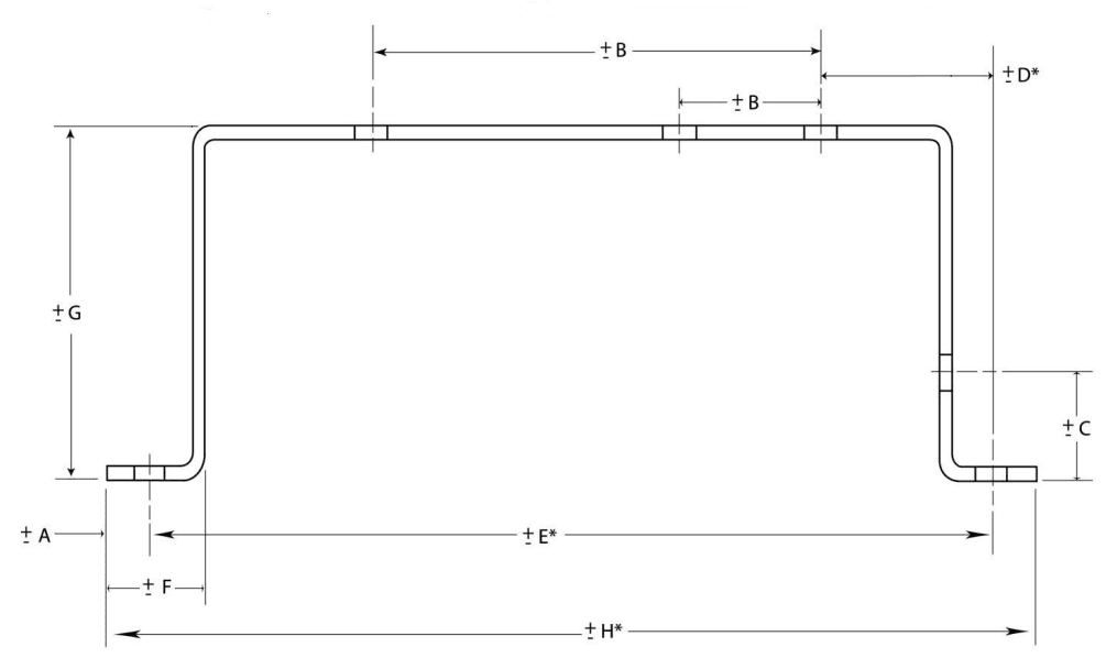
| DIM | Tolerance (MM) | Tolerance (Inches) | Description |
| A | ± 0.13 | ± 0.005 | Sheared Edge to Hole |
| B | ± 0.13 | ± 0.005 | 2 Holes on One Surface |
| C | ± 0.25 | ± 0.010 | Formed Edge to Hole |
| D* | ± 0.76 | ± 0.030 | Holes Across 2 Bends |
| E* | ± 0.76 | ± 0.030 | Holes Across 4 Bends |
| F | ± 0.25 | ± 0.010 | Sheared Edge to Bend |
| G | ± 0.38 | ± 0.015 | Across 2 Bends |
| H* | ± 0.76 | ± 0.030 | Formed Part |
Noted dimensions are to be taken while the part is in a restrained condition. Noted dimensions are for parts within a 12” envelope.
* Dimensions D, E and H are not recommended forms of dimensioning
These tolerances are recommended and best practices. We can obtain tighter tolerances (depending on part geometry/ construction), contact us for more information


